


Digital Encoder Circuit Using Stepper Motor
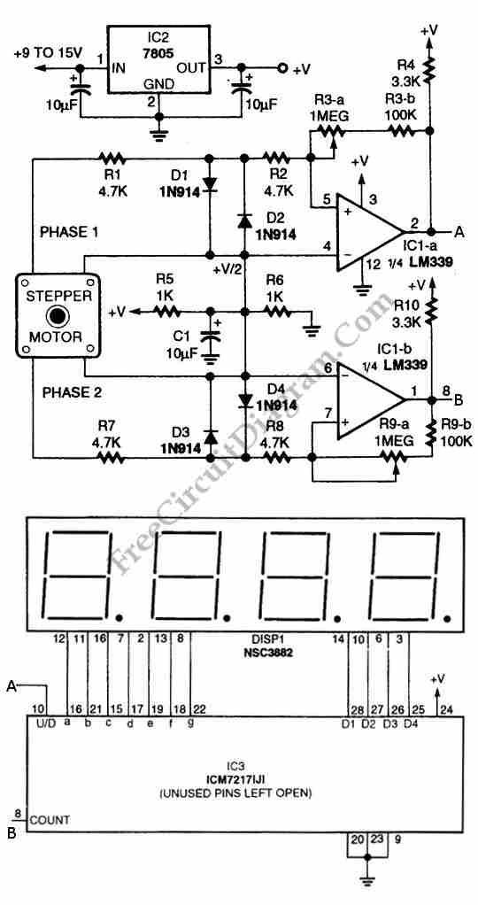
Description: The circuit illustrated in the schematic diagram below allows for the visualization of the direction and shaft rotation of a stepper motor on an LED display. Instead of employing a digital rotation encoder as an input, this circuit utilizes a stepper motor. Here is the schematic diagram of the circuit:
The circuit operates by utilizing a stepper motor, which is a type of motor that divides a full rotation into a number of equal steps. This allows for precise control of the motor's position and speed. The LED display serves as a visual output, indicating the current direction of rotation and the specific position of the motor shaft.
The schematic typically includes a microcontroller that processes input signals and determines the appropriate step sequence for the stepper motor. The microcontroller interfaces with the motor driver, which amplifies the control signals to drive the motor coils. The stepper motor is connected to the driver in a configuration that allows for full-step or half-step operation, depending on the desired resolution.
The LED display is connected to the microcontroller, which sends signals to illuminate specific segments of the display based on the motor's position and direction of rotation. This feedback mechanism is crucial for applications where precise motor control and real-time monitoring are necessary.
In summary, this circuit effectively combines a stepper motor with an LED display to provide a comprehensive solution for visualizing motor position and direction, replacing the need for more complex digital encoders while maintaining accuracy and reliability in motor control applications.Using circuit depicted in the schematic diagram below, the direction and shaft rotation of stepper motor can be seen on the LED display. Alternative to digital rotation encoder as a digital encoder input, this circuit uses a stepper motor.
Here is the schematic diagram of the circuit:
The circuit operates by utilizing a stepper motor, which is a type of motor that divides a full rotation into a number of equal steps. This allows for precise control of the motor's position and speed. The LED display serves as a visual output, indicating the current direction of rotation and the specific position of the motor shaft.
The schematic typically includes a microcontroller that processes input signals and determines the appropriate step sequence for the stepper motor. The microcontroller interfaces with the motor driver, which amplifies the control signals to drive the motor coils. The stepper motor is connected to the driver in a configuration that allows for full-step or half-step operation, depending on the desired resolution.
The LED display is connected to the microcontroller, which sends signals to illuminate specific segments of the display based on the motor's position and direction of rotation. This feedback mechanism is crucial for applications where precise motor control and real-time monitoring are necessary.
In summary, this circuit effectively combines a stepper motor with an LED display to provide a comprehensive solution for visualizing motor position and direction, replacing the need for more complex digital encoders while maintaining accuracy and reliability in motor control applications.Using circuit depicted in the schematic diagram below, the direction and shaft rotation of stepper motor can be seen on the LED display. Alternative to digital rotation encoder as a digital encoder input, this circuit uses a stepper motor.
Here is the schematic diagram of the circuit:
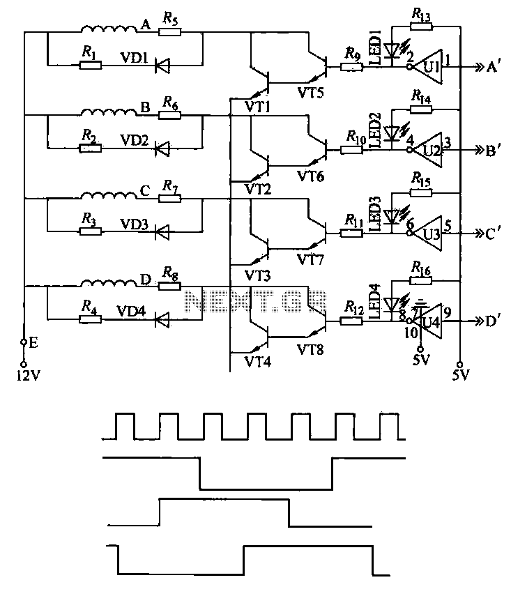
Stepper motor control circuit
This machine utilizes the FD-CAS-923 1-stepper motor control experiment board with a 4-phase stepper motor to avoid its schematic shown in Figure 4-42a. The JK1 cop 40 core flat cable connector allows for signal arrangements compatible with EICE51 simulation interfaces,...
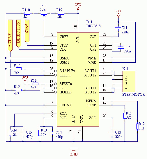
stepper motor control
The 3D printer necessitates independent control for three separate axes. Each controlled axis must be equipped with a high-precision electronic driver. The mechanical components of each axis utilize a precise bipolar stepper motor connected to a drive shaft via a...
.jpg "TB6600 5A Single Axis 5A CNC Stepper Driver For CNC Milling Machine DIY Max 50V circuit")
TB6600 5A Single Axis 5A CNC Stepper Driver For CNC Milling Machine DIY Max 50V
This is a two-phase hybrid stepping motor with a dynamic voltage range of 12 to 48V and a maximum current rating of less than 5A. The motor has an outer diameter ranging from 35 to 86 mm. The drive employs...
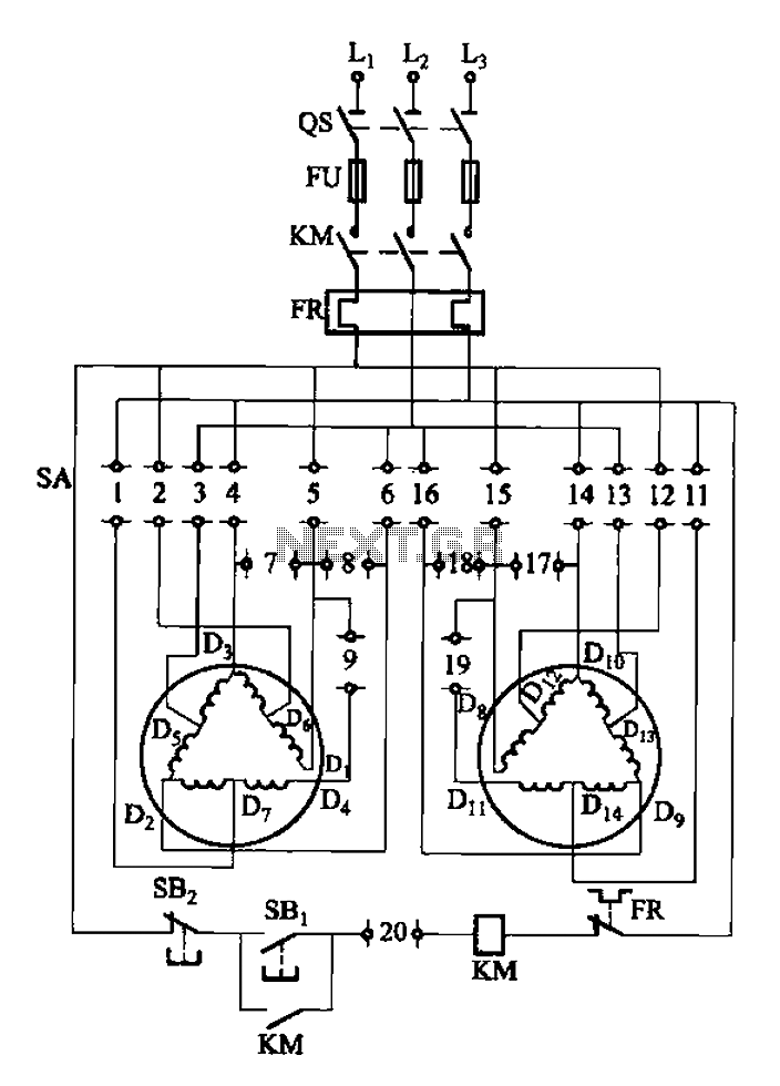
2Y-Y-2 - connection four-speed motor switch control circuit
The 3-119 circuit shown in the figure combines switch SA to realize the stator windings, specifically the 2, Y, and 2Y connections, which correspond to the motor speed n1.
The 3-119 circuit is designed to facilitate the control of motor speed...
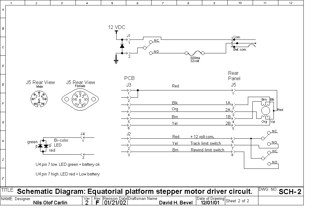
Stepper
The resistors R18 and R22, which were intended to be connected to pin 8 of U4, were incorrectly connected to pin 9. The current versions have been corrected. There is a minor error in the component layout where two versions...
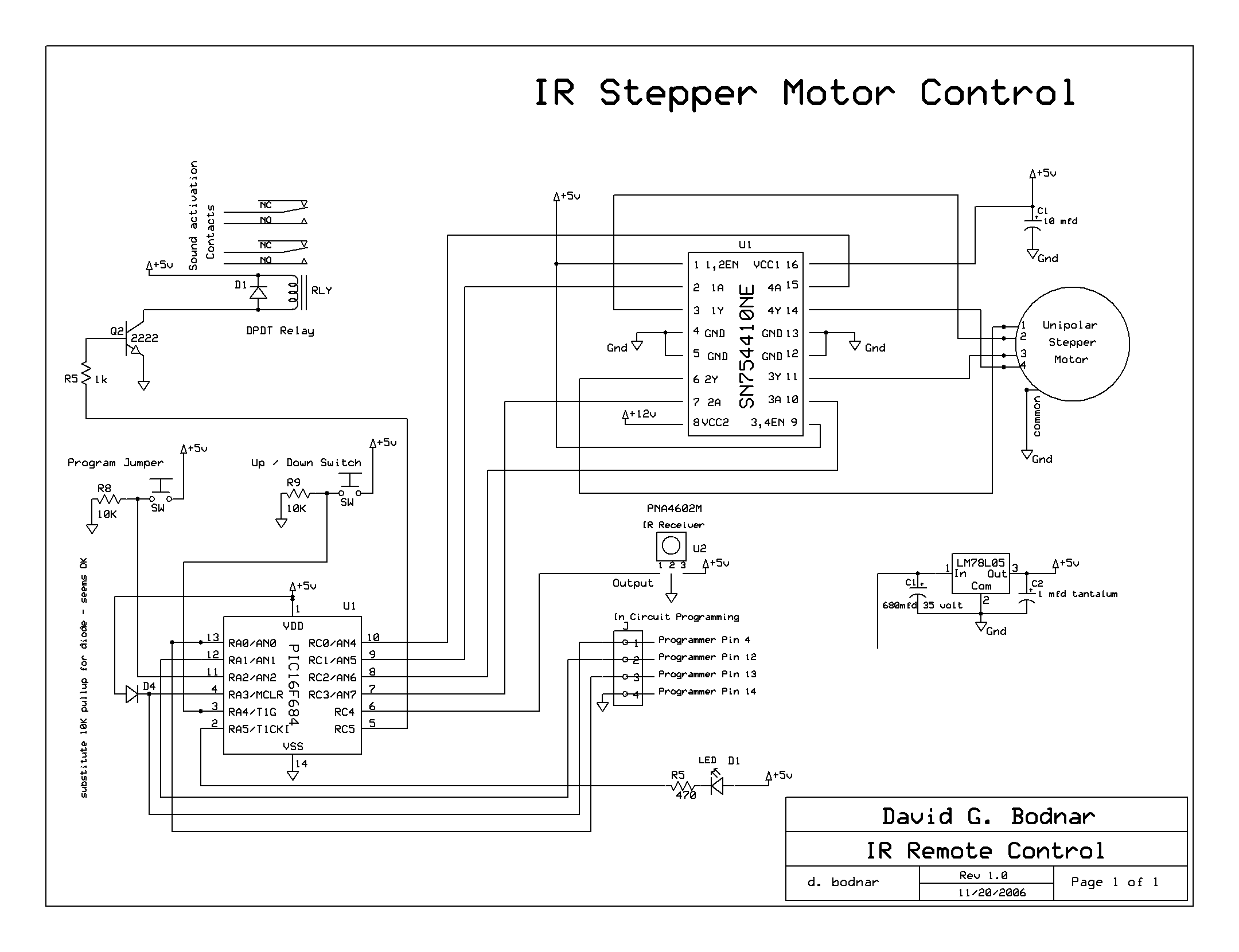
Stepper Motor Project
The microcontroller board is displayed (top left/green board) alongside the auxiliary board (bottom left/brown board) and two geared Hurst stepper motors. In this view, the programming jumper is located in the upper right area of the microcontroller board, while power...
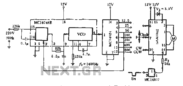
SAA1042 stepper motor control circuit
A typical application example is presented, demonstrating the SAA1042 12V stepper motor drive configuration. The phase winding current is set at 200mA. According to RB Figure 5-10, a resistor value of RE = 56kΩ is selected. This resistor is connected...
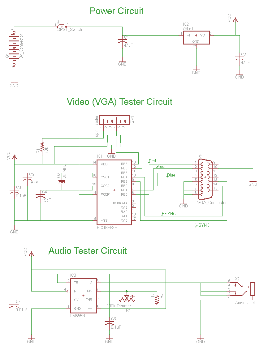
DIY Stepper Controller Circuit
The schematic for the board is illustrated below. The three primary components of the board include (1) the power input and voltage regulation, (2) the L297 input and outputs, and (3) the L298 stepper motor control circuit. The motor is...
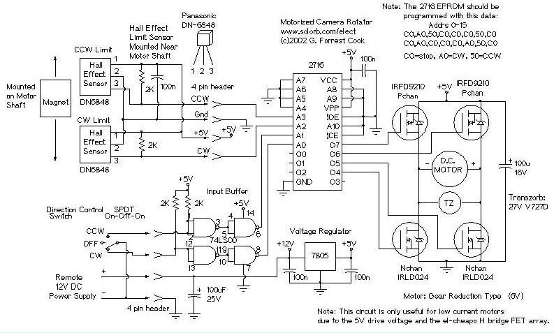
Motorized Video Camera Mount
The camera rotator circuit utilizes a 2716 EPROM to store a logic value table that governs the motor driver (H-bridge) circuit. The schematic illustrates the EPROM data. By employing the EPROM, a significant number of discrete gates are eliminated. The...