


Door lock Motor
#L293B
#motor driver
#voltage regulator
#LM7805
#door lock
#DC motor
#current limit
#5V power supply
#high current
#short duration operation
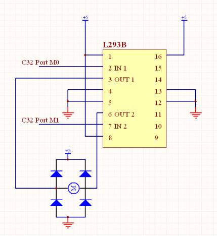
Description: The measured resistance of the door lock motor was approximately 2 ohms. Consequently, when supplied with 5V, the current is calculated as 5V/2Ω = 2.5A. Considering that the peak output current of the L293B is 2A, the current flowing through the motor slightly exceeds 2A; however, this is not problematic as the motor will only be utilized for a few seconds. A voltage regulator (LM7805) was employed to step down the voltage from 14V to 5V. The peak output current of the LM7805 is 2.5A when the voltage difference between the input and output is 9V (14V - 5V = 9V). Therefore, the LM7805 can provide sufficient current for the door lock motor.
The circuit under discussion involves a door lock motor with a resistance of approximately 2 ohms, which draws a current of 2.5A when powered by a 5V supply. This current is slightly above the maximum continuous output of the L293B motor driver, which is rated at 2A. However, since the motor is intended to operate only for brief intervals, this temporary overload does not pose a significant risk to the driver.
To effectively manage the power supply, a voltage regulator, specifically the LM7805, is utilized to convert a higher voltage of 14V down to the required 5V for the motor. The LM7805 is capable of delivering a peak output current of 2.5A, sufficient to meet the demands of the motor operation under the specified conditions. It is essential to note that the LM7805's output capacity is contingent upon the voltage differential; it can deliver its maximum current when the input voltage exceeds the output voltage by at least 9V. This ensures that the regulator operates within its safe limits while providing adequate power to the motor.
In summary, the circuit successfully integrates a door lock motor with a power supply system that includes a motor driver and a voltage regulator, allowing for efficient operation while maintaining component safety and reliability during short-duration tasks.The measured resistance of door lock motor was about 2 ohm. Therefore, supplying 5V, the current becomes 5v/2ohm= 2. 5A. Regarding that the peak output current of L293B is 2A, the current flowing inside the motor is slightly over 2A, but it does not occur any problem because the motor will be used just for several seconds. Voltage regulator (LM7805 ) was used to regulate the voltage from 14V to 5V. 7805`s peak output current is 2. 5A when the voltage difference between the input and the output is 9V (14-5=9V). Therefore 7805 can supply enough current for door lock motor.
The circuit under discussion involves a door lock motor with a resistance of approximately 2 ohms, which draws a current of 2.5A when powered by a 5V supply. This current is slightly above the maximum continuous output of the L293B motor driver, which is rated at 2A. However, since the motor is intended to operate only for brief intervals, this temporary overload does not pose a significant risk to the driver.
To effectively manage the power supply, a voltage regulator, specifically the LM7805, is utilized to convert a higher voltage of 14V down to the required 5V for the motor. The LM7805 is capable of delivering a peak output current of 2.5A, sufficient to meet the demands of the motor operation under the specified conditions. It is essential to note that the LM7805's output capacity is contingent upon the voltage differential; it can deliver its maximum current when the input voltage exceeds the output voltage by at least 9V. This ensures that the regulator operates within its safe limits while providing adequate power to the motor.
In summary, the circuit successfully integrates a door lock motor with a power supply system that includes a motor driver and a voltage regulator, allowing for efficient operation while maintaining component safety and reliability during short-duration tasks.The measured resistance of door lock motor was about 2 ohm. Therefore, supplying 5V, the current becomes 5v/2ohm= 2. 5A. Regarding that the peak output current of L293B is 2A, the current flowing inside the motor is slightly over 2A, but it does not occur any problem because the motor will be used just for several seconds. Voltage regulator (LM7805 ) was used to regulate the voltage from 14V to 5V. 7805`s peak output current is 2. 5A when the voltage difference between the input and the output is 9V (14-5=9V). Therefore 7805 can supply enough current for door lock motor.
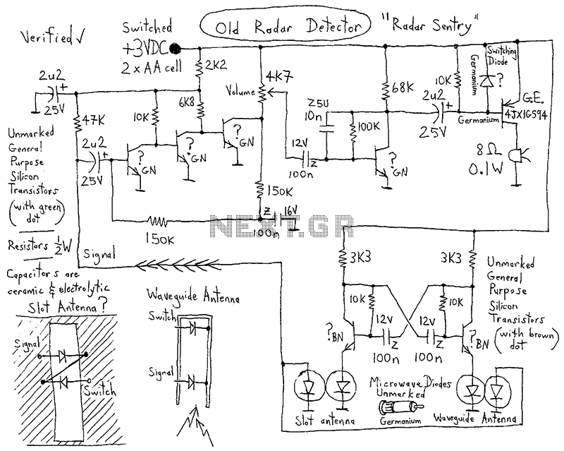
Bathroom Deoderizer Control
This device features a small DC motor fan situated above a container filled with deodorant liquid or gel, powered by a D cell battery. A photocell is integrated to deactivate the fan in low light conditions. An LED indicator flashes...
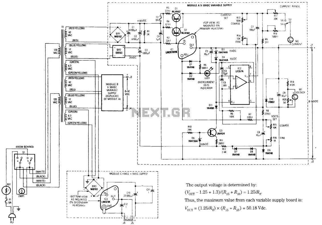
Universal Laboratory Power Supply Circuit
The design's value is derived from the use of IC1, an LM317HVK adjustable series-pass voltage regulator, which provides broad-range performance along with voltage-setting and current-limiting functions. The input to IC1 is sourced from the output of BR1, which is filtered...
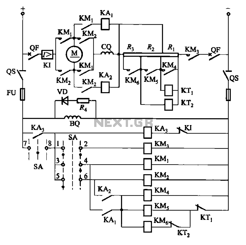
One of reversing circuit reverse braking resistor in series with a DC motor armature start
The circuit depicted in Figure 3-201 includes two starting resistors, with one controlled by a time relay. A master switch (SA) is utilized to manage the motor's reversing operation. The circuit incorporates a reverse braking mechanism, which is automatically controlled...
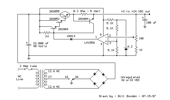
Variable 3 - 24 Volt / 3 Amp Power Supply circuit
This regulated power supply can be adjusted from 3 to 25 volts and is current limited to 2 amps as shown, but may be increased to 3 amps or more by selecting a smaller current sense resistor (0.3 ohm). The...

voltage regulator circuit with pass
This is a simple design for a voltage regulator circuit using a pass transistor. The design is built around the LM317T. The output current of the LM317T can be increased by incorporating an additional power transistor to share a portion...
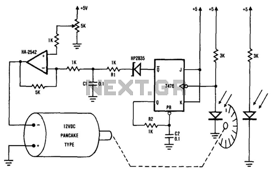
Dc Motor-Speed Control
The system comprises the HA-2542 operational amplifier, a compact 12 V DC motor, and a position encoder. During operation, the encoder generates a series of constant-width pulses that charge capacitor C1. These integrated pulses create a reference voltage proportional to...
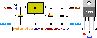
9 Volt 2 Ampere DC Power SupplyCircuit
A simple 9 Volt, 2 amp power supply utilizing a single integrated circuit (IC) regulator. This circuit is straightforward, as the regulator handles the majority of the work. The component used is the 7809 voltage regulator.
The circuit consists primarily of...
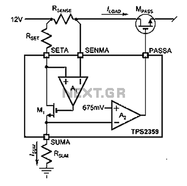
Payload power current limit circuit diagram
Amplifier A1 utilizes the voltage across the sense resistor sensors to monitor the load current ILOAD. The power management channel employs a similar circuit, with the distinction of integrating resistors RSENSE and RSET.
Amplifier A1 is configured to measure the load...
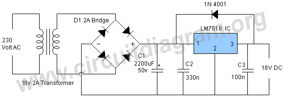
18v power supply using lm7818
This power supply operates effectively to provide a stable 18V DC output with a maximum current of 1.5A. The circuit employs an LM7818 positive voltage regulator integrated circuit (IC), which includes several built-in features such as internal current limiting, short...