


Electrical control circuit plow
#agriculture
#plow
#ground wire
#traction machine
#electrical power
#rubber cable
#motor
#control circuit
#safety
#grounding
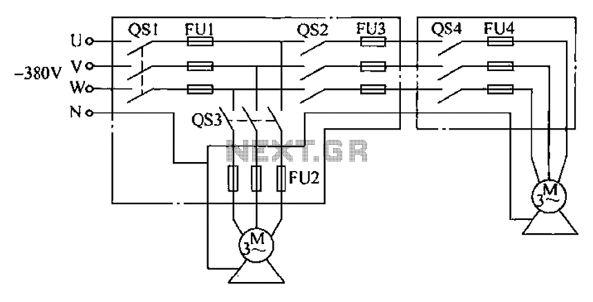
Description: The agriculture and electrical power harrow plow power cord must consist of four rubber cables, with one core wire designated as the ground wire. The traction machine housing must be properly grounded. The two traction power machines are connected to the same distribution box on the farm via a four-core cable branch box, which supplies power to the two tractor power steering switches. As illustrated in Figure 8-9, the sub-branch box features three cable outlet holes, and the cables should be secured to these holes to prevent accidental disconnection. The power splitter box, which should be made of metal, must also be grounded and provide convenient connections for the two tractor positions. After use, the power cord should be promptly removed.
In agricultural applications, ensuring the safety and reliability of electrical connections is paramount. The design of the power cord system for the harrow plow incorporates four rubber cables to withstand harsh environmental conditions typically found in farming settings. Among these cables, one is specifically designated as a ground wire, which is critical for preventing electrical shock hazards and ensuring the safe operation of the equipment.
The traction machine housing must be grounded effectively to facilitate the safe dissipation of any electrical faults. This is achieved by connecting the ground wire to a suitable grounding point, which could be an earth stake or a metal structure that is in contact with the ground.
The power distribution system utilizes a four-core cable branch box that connects to the farm's main power supply. This branch box serves as a central hub from which power is distributed to two separate traction power machines. Each machine is equipped with a dedicated power steering switch, allowing for independent operation while ensuring that both machines can be powered from a single source.
The sub-branch box is designed with three outlet holes to accommodate the cables leading to the traction machines. To maintain a secure connection and prevent accidental disconnection, the cables should be properly tied to these holes. This precaution is essential, especially in dynamic agricultural environments where movement and vibrations are common.
The power splitter box, constructed from durable metal, not only provides structural integrity but also ensures that the system remains grounded. This grounding is vital for protecting the equipment and operators from potential electrical hazards. The design of the splitter box allows for easy and convenient connections, facilitating quick setup and adjustments between the two tractor positions.
Finally, it is important to emphasize the necessity of promptly removing the power cord after use. This practice not only prevents potential tripping hazards but also minimizes the risk of damage to the cables or the equipment, thereby enhancing the longevity and reliability of the electrical system in agricultural operations.Agriculture and electrical power harrow plow power cord must be used four rubber cable, wherein a core wire as a ground wire, traction machine housing must be grounded. Two tra ction power machine is a quote from the same distribution box in the farms out of a four-core cable branch box to the power supply, power points as a branch box into two (respectively to the two tractor power steering switch on). As shown in Figure 8-9. In sub- branch box, cable outlet opening three holes, the cable leads should tie the hole to prevent the plug off on their own.
Power splitter box support such as metal, must be grounded and provided convenient connection of two tractor position. After use, the power cord should be promptly removed.
In agricultural applications, ensuring the safety and reliability of electrical connections is paramount. The design of the power cord system for the harrow plow incorporates four rubber cables to withstand harsh environmental conditions typically found in farming settings. Among these cables, one is specifically designated as a ground wire, which is critical for preventing electrical shock hazards and ensuring the safe operation of the equipment.
The traction machine housing must be grounded effectively to facilitate the safe dissipation of any electrical faults. This is achieved by connecting the ground wire to a suitable grounding point, which could be an earth stake or a metal structure that is in contact with the ground.
The power distribution system utilizes a four-core cable branch box that connects to the farm's main power supply. This branch box serves as a central hub from which power is distributed to two separate traction power machines. Each machine is equipped with a dedicated power steering switch, allowing for independent operation while ensuring that both machines can be powered from a single source.
The sub-branch box is designed with three outlet holes to accommodate the cables leading to the traction machines. To maintain a secure connection and prevent accidental disconnection, the cables should be properly tied to these holes. This precaution is essential, especially in dynamic agricultural environments where movement and vibrations are common.
The power splitter box, constructed from durable metal, not only provides structural integrity but also ensures that the system remains grounded. This grounding is vital for protecting the equipment and operators from potential electrical hazards. The design of the splitter box allows for easy and convenient connections, facilitating quick setup and adjustments between the two tractor positions.
Finally, it is important to emphasize the necessity of promptly removing the power cord after use. This practice not only prevents potential tripping hazards but also minimizes the risk of damage to the cables or the equipment, thereby enhancing the longevity and reliability of the electrical system in agricultural operations.Agriculture and electrical power harrow plow power cord must be used four rubber cable, wherein a core wire as a ground wire, traction machine housing must be grounded. Two tra ction power machine is a quote from the same distribution box in the farms out of a four-core cable branch box to the power supply, power points as a branch box into two (respectively to the two tractor power steering switch on). As shown in Figure 8-9. In sub- branch box, cable outlet opening three holes, the cable leads should tie the hole to prevent the plug off on their own.
Power splitter box support such as metal, must be grounded and provided convenient connection of two tractor position. After use, the power cord should be promptly removed.
Tachometerless Motor Speed Control
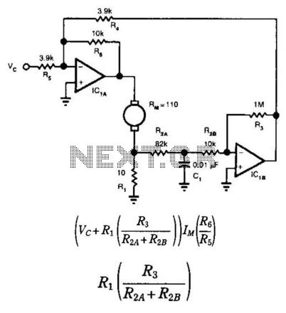
This circuit provides bidirectional speed regulation for small motors and does not require a tachometer. The voltage applied to the motor's windings, which is determined by summing amplifier IC1A, is expressed as a function of the command voltage (Vc) and...
Night Safety Light For Autos
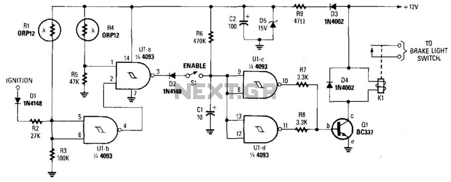
This circuit activates the brake lights of a parked car when headlights from an approaching vehicle are detected, alerting the driver of the oncoming vehicle about the stationary car. LDR4 serves as the sensor, while LDR1 deactivates the circuit by...
The use of a motor control switch automatic circuit a mutual investment
The circuit illustrated in Figure 3-64 operates with switch SA1 in the work position and switch SA2 in the standby position, allowing motor Mi to run while motor Mz remains on standby. In the event of downtime for motor Mi,...
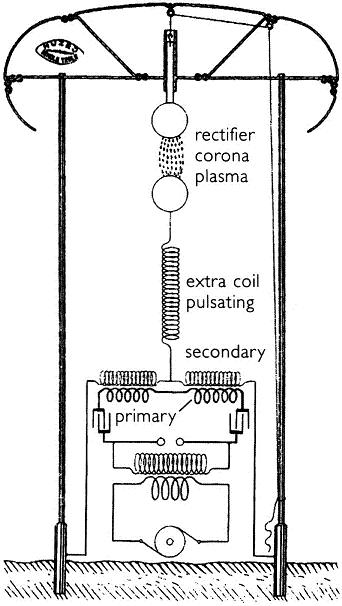
Gray Tube Replication 85
The information regarding operating the motor without the tubes is new to the individual. There is a desire to learn more about this subject.
The operation of a motor without the use of tubes can be a significant topic in the...
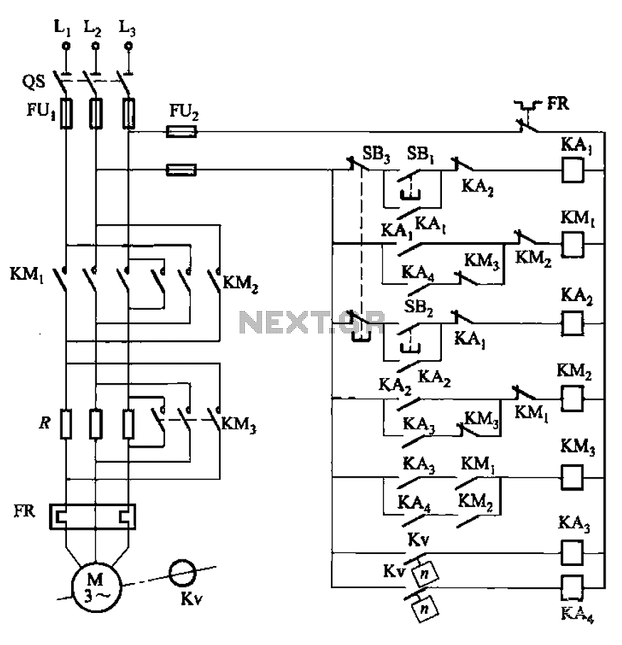
Three reversing operation of the reverse brake circuit
The circuit illustrated in Figure 3-130 differs from the circuit in Figure 3-129 in that when the stop button SB3 is pressed, the electric motor initiates braking. Furthermore, during both the startup and braking phases, the motor power lines are...
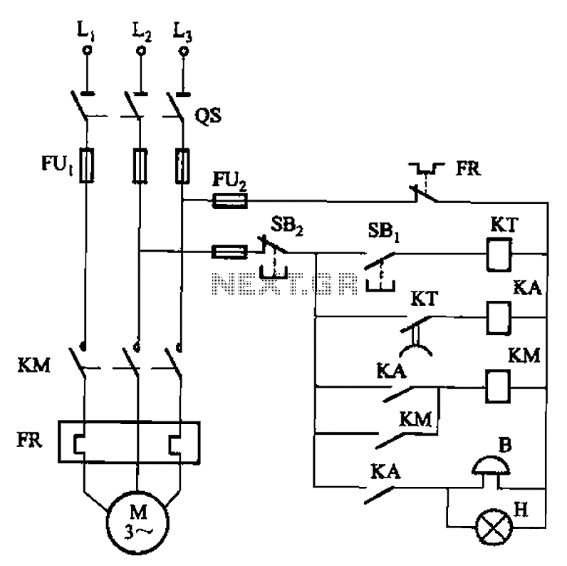
It can send a signal to start forward rotation start circuit
The circuit shown in Figure 3-21 is designed to produce a motor startup sound and a light signal indicating the completion of the startup process, after which the signal ceases. This circuit is tailored to control the motor for a...
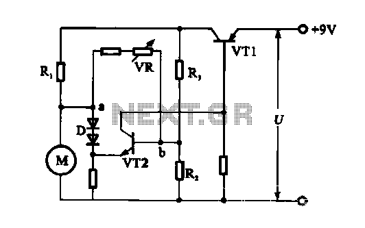
Electronic circuit steady speed motor application
The electronic circuit for steady speed motor applications utilizes an automatic remote control system to regulate the motor power supply, thereby achieving consistent speed control. The circuit diagram illustrates a DC motor connected to the system. Given that the DC...
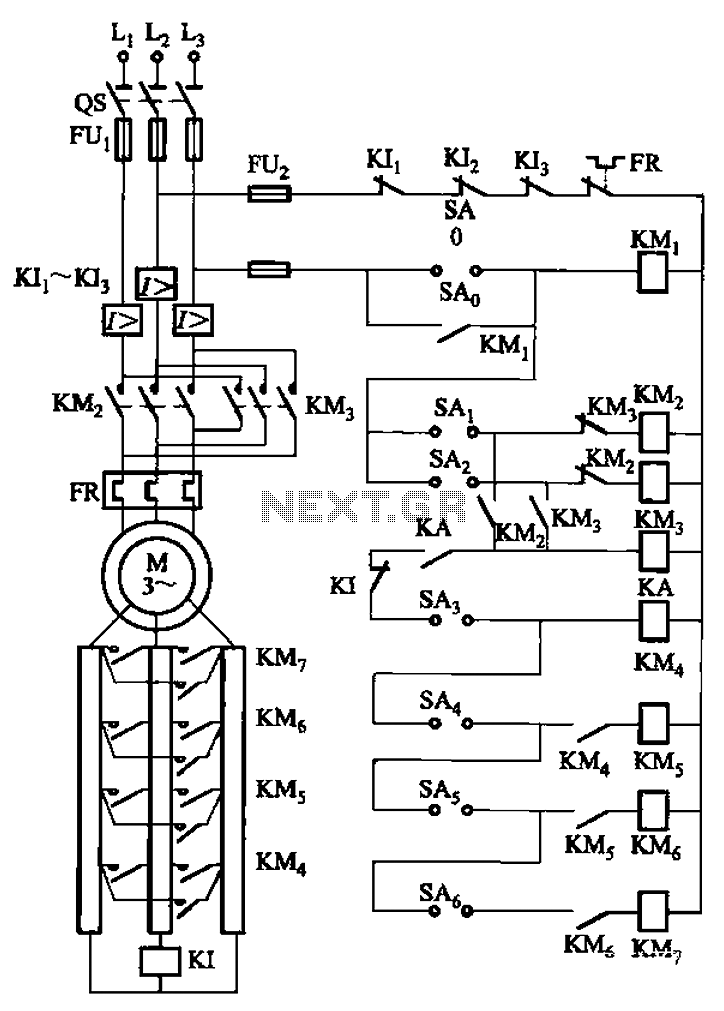
A control circuit reversing braking and reverse grading speed control function
The circuit depicted in Figure 3-168 utilizes a controller for speed grading and reversing control. A reverse brake is connected to the rotor circuit through an overcurrent relay, labeled KI, for control. The current relay KIi to KI3 serves as...
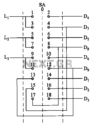
Switching two-speed motor control circuit
The motor switch control circuit depicted in the figure provides two speed settings for counter-steering, allowing for operation at two speeds in opposite directions.
The motor switch control circuit is designed to facilitate the operation of a motor at two distinct...