


Extended delta decompression starter control circuit
#motor starter
#delta decompression
#three-phase winding
#motor control
#starter circuit
#industrial motor
#electrical engineering
#power electronics
#wiring
#motor protection
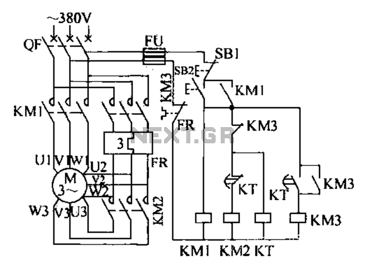
Description: The extended delta decompression starter is designed to manage the operation of a three-phase motor during startup. It involves the initial connection of the motor's three-phase winding set to facilitate a reduced voltage startup, which is achieved through a coupling mechanism linked to an additional set of contacts. The extended delta windings enable the motor starter to transition the three-phase stator windings into a coupled operation. The control circuit for the extended delta decompression starter is illustrated in a referenced figure. Upon startup, pressing the start button (SB2) energizes the KM1 contactor, which then locks in place. This allows the three-phase power supply to connect through the KM1 main contact to the motor's outlet terminals (U1, V1, W1). Concurrently, the KM2 contactor is energized, closing its main contacts and linking the additional terminals (U2, V2, W2, U3, V3, W3) to the motor for a reduced voltage start. After a predetermined delay, the KT coil is activated, causing the KT contacts to open and de-energize the KM2 contactor, disconnecting the reduced voltage connections. The KT normally open contact then closes, energizing the KM3 contactor, which reconnects the stator windings for full voltage operation of the motor.
The extended delta decompression starter is an essential component in the control of three-phase induction motors, particularly in applications where high starting torque and reduced mechanical stress are necessary. The circuit employs a combination of contactors and relays to facilitate a smooth transition from a reduced voltage startup to full operational voltage, thereby minimizing inrush currents and preventing damage to the motor and connected equipment.
The operation begins with the pressing of the start button (SB2), which activates the KM1 contactor. This contactor serves as the primary control element, establishing a connection between the power supply and the motor. The self-locking feature of KM1 ensures that once energized, the contactor remains engaged, providing a continuous power supply to the motor.
Simultaneously, the KM2 contactor is also activated, allowing the motor to operate at a lower voltage by connecting the additional winding terminals (U2, V2, W2, U3, V3, W3). This configuration reduces the voltage applied to the motor, which is critical during the startup phase to limit the mechanical and electrical stress on the system.
The delay period, controlled by the KT coil, is a crucial aspect of this circuit. It allows the motor to reach a stable operating condition at the reduced voltage before transitioning to full voltage. Once the delay expires, the KT contacts open, de-energizing the KM2 contactor and removing the reduced voltage connections. The closing of the KT normally open contact activates the KM3 contactor, which then reconnects the motor stator windings for full voltage operation.
This method of starting a three-phase motor not only enhances the reliability and longevity of the motor but also improves energy efficiency by reducing the initial current draw. The extended delta decompression starter is particularly beneficial in applications where the motor is subject to frequent starts and stops, as it mitigates the risk of overheating and mechanical failure.Extended delta decompression starter, that is, when the motor starts its three -phase winding set to take part, eatY coupling, connected to another part of links, the entire ex tended delta windings are to be completed motor starter, three-phase stator windings into coupling operation. Extended delta decompression starter control circuit shown in Figure 4u 13. Start-up, press the start button SB2, KM1 contactor is energized and self-locking, three-phase power supply via KM1 main contact is connected to the outlet side of the motor 3 Ul, Vl, Wl.
Meanwhile contactor KM2 was electric pull, KM2 main contact is closed, respectively, U2, V3, V2, W3, W2, U3 connected Yanbian j angle, electric pressure machine start. At the same time, KT coil is energized, after a delay period of time, often wide KT j contacts disconnect power contactor KM2 release, U2, V3, V2, w3, W2, U3 uncoupled; KT normally open contact closure, KM3 was electric pull.
Respectively Ul, w2, f, U2, Wl, V2 reconnect the stator winding connected into coupling into the motor full voltage operation.
The extended delta decompression starter is an essential component in the control of three-phase induction motors, particularly in applications where high starting torque and reduced mechanical stress are necessary. The circuit employs a combination of contactors and relays to facilitate a smooth transition from a reduced voltage startup to full operational voltage, thereby minimizing inrush currents and preventing damage to the motor and connected equipment.
The operation begins with the pressing of the start button (SB2), which activates the KM1 contactor. This contactor serves as the primary control element, establishing a connection between the power supply and the motor. The self-locking feature of KM1 ensures that once energized, the contactor remains engaged, providing a continuous power supply to the motor.
Simultaneously, the KM2 contactor is also activated, allowing the motor to operate at a lower voltage by connecting the additional winding terminals (U2, V2, W2, U3, V3, W3). This configuration reduces the voltage applied to the motor, which is critical during the startup phase to limit the mechanical and electrical stress on the system.
The delay period, controlled by the KT coil, is a crucial aspect of this circuit. It allows the motor to reach a stable operating condition at the reduced voltage before transitioning to full voltage. Once the delay expires, the KT contacts open, de-energizing the KM2 contactor and removing the reduced voltage connections. The closing of the KT normally open contact activates the KM3 contactor, which then reconnects the motor stator windings for full voltage operation.
This method of starting a three-phase motor not only enhances the reliability and longevity of the motor but also improves energy efficiency by reducing the initial current draw. The extended delta decompression starter is particularly beneficial in applications where the motor is subject to frequent starts and stops, as it mitigates the risk of overheating and mechanical failure.Extended delta decompression starter, that is, when the motor starts its three -phase winding set to take part, eatY coupling, connected to another part of links, the entire ex tended delta windings are to be completed motor starter, three-phase stator windings into coupling operation. Extended delta decompression starter control circuit shown in Figure 4u 13. Start-up, press the start button SB2, KM1 contactor is energized and self-locking, three-phase power supply via KM1 main contact is connected to the outlet side of the motor 3 Ul, Vl, Wl.
Meanwhile contactor KM2 was electric pull, KM2 main contact is closed, respectively, U2, V3, V2, W3, W2, U3 connected Yanbian j angle, electric pressure machine start. At the same time, KT coil is energized, after a delay period of time, often wide KT j contacts disconnect power contactor KM2 release, U2, V3, V2, w3, W2, U3 uncoupled; KT normally open contact closure, KM3 was electric pull.
Respectively Ul, w2, f, U2, Wl, V2 reconnect the stator winding connected into coupling into the motor full voltage operation.

5-motor hexapod circuit
This circuit has a long history, originating from an idea by Rich Piotter and later refined by Wilf Rigter and Bruce Robinson. The final result does not include the necessary motor drivers, which are typically H-bridge based, but presents a...
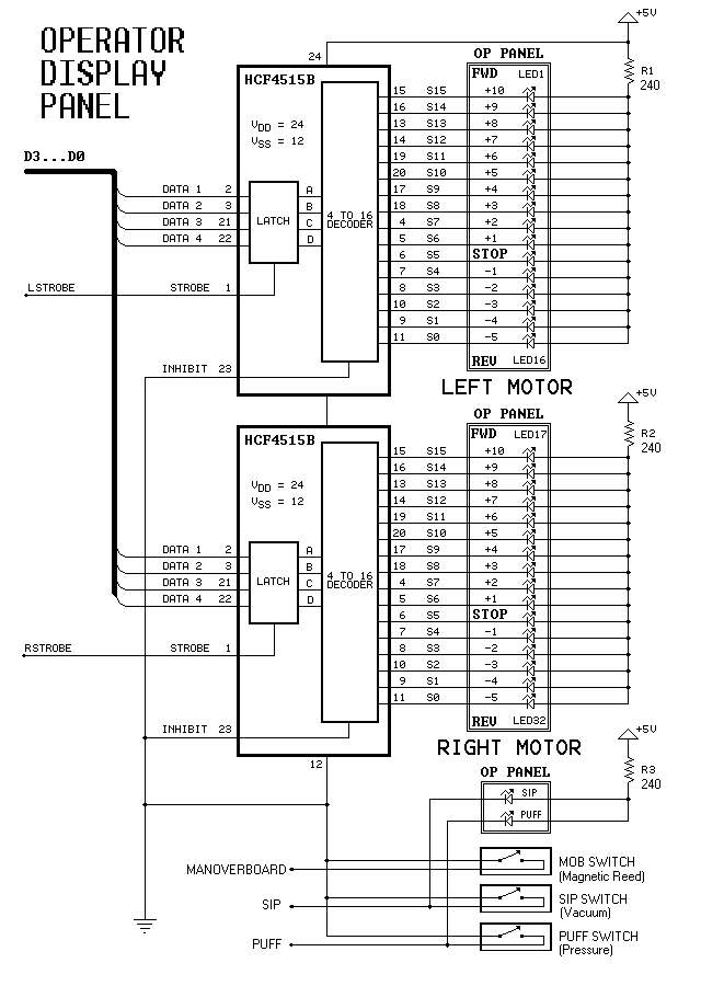
Dual-Motor SIP&PUFF Controlled Kayak System
The YouTube video below demonstrates the quick and easy setup of the system at the launch site.
The provided description indicates a focus on the efficiency of system installation at a launch site, as showcased in a YouTube video. In an...
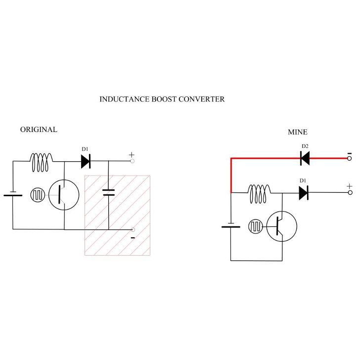
My Motors got me to Tap into Radiant Energy
A new user is seeking to share information about their experiences on this platform.
The user expresses a desire to communicate and engage with the community regarding their experiences. This indicates an interest in exchanging knowledge and possibly seeking assistance or...
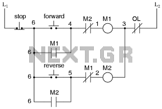
Motor control circuit for forward and reverse phase induction
This is the power diagram for motor forward and reverse operation. To change the motor direction, one polarity must be altered, for example, changing R to S. For detailed information, please refer to the following.
The described power diagram illustrates a...
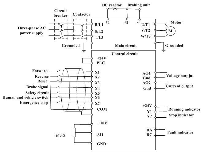
motor control inverter (AC drive) in mine industry
Motor control, energy efficiency of inverter (AC drive) selection, and parameters setting guidance in the mining industry: vector control, open loop or closed loop control, with energy braking unit or energy feedback unit.
In the context of motor control for the...
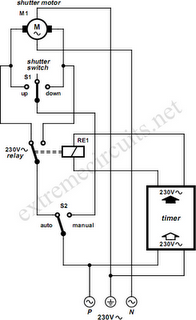
To Automate Rolling Shutter Motor
To automate the opening and closing of a rolling shutter using a time-controlled switch, additional wiring will be necessary.
To implement an automated system for a rolling shutter, a time-controlled switch can be utilized to manage the operation of the shutter....
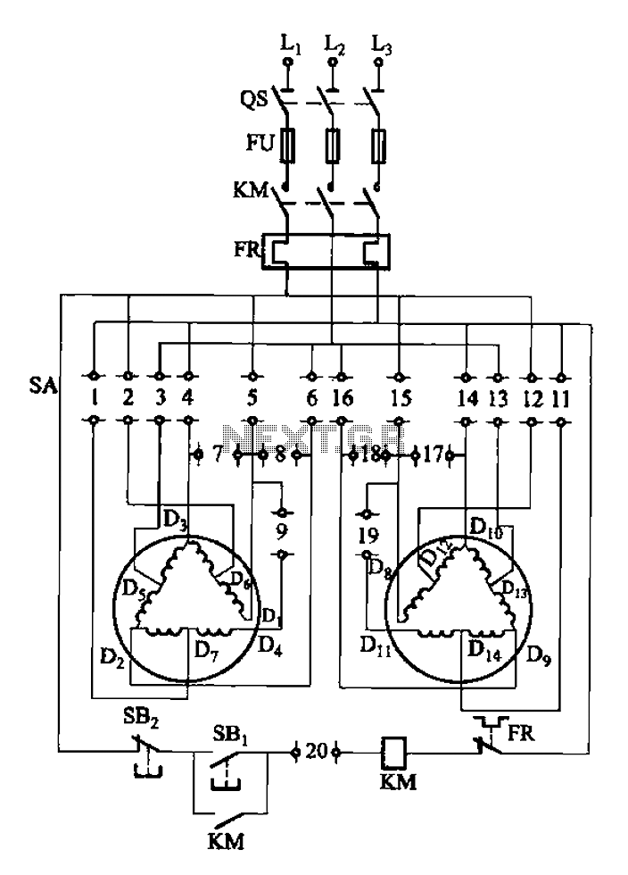
2Y-Y-2 - connection four-speed motor switch control circuit
The 3-119 circuit shown in the figure combines switch SA to realize the stator windings, specifically the 2, Y, and 2Y connections, which correspond to the motor speed n1.
The 3-119 circuit is designed to facilitate the control of motor speed...
Gray Projects
After learning to operate the device, it became evident that inertia posed a significant challenge. The constructed system is notably heavy, making it difficult to initiate motor operation at full speed. Despite having some understanding of physics, practical experience is...
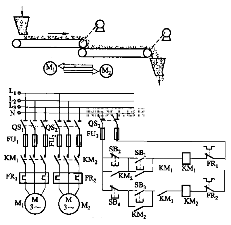
Belt conveyor interlock motor operation sequence control circuit
The circuit depicted in Figure 3-86 utilizes a line utilization time relay to control two motors, starting one before the other after an initial stall. The time relay KTi can be adjusted to modify the starting interval of the two...