


F/V Converter in CLosed Loop Motor Speed Control System
#closed loop
#servo system
#F/V converter
#speed control
#feedback
#motor
#control system
#stabilization
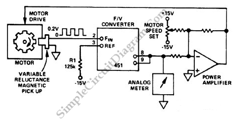
Description: A closed-loop or servo system has the capability to stabilize the controlled plant at a specified operating condition. The plant, which is the controlled sub-system, can be...
A closed-loop control system, commonly referred to as a servo system, is designed to maintain a desired output by continuously monitoring and adjusting the input based on feedback from the system. This type of system is essential in applications where precise control is required, such as in robotics, industrial automation, and aerospace engineering.
In a typical closed-loop system, the key components include a controller, a sensor, an actuator, and the plant itself. The controller processes the error signal, which is the difference between the desired setpoint and the actual output measured by the sensor. The controller then generates a control signal that is sent to the actuator, which modifies the input to the plant to achieve the desired output.
The plant represents the process or system being controlled, which can include mechanical, electrical, thermal, or fluid systems. The stability of the closed-loop system is crucial; it ensures that the output remains within the desired range even in the presence of disturbances or changes in system dynamics.
Feedback mechanisms play a vital role in maintaining system stability. Positive feedback can lead to instability, while negative feedback is employed to reduce the error signal and stabilize the system. Various control strategies, such as proportional-integral-derivative (PID) control, are often implemented to enhance the performance of closed-loop systems by optimizing the response time and minimizing overshoot.
Overall, closed-loop systems are fundamental in modern engineering, enabling precise control and automation across a wide range of applications.Closed loop or servo system has the ability to stabilize the controlled plant at a specified operating condition. The plant, the controlled sub-system, can be..
A closed-loop control system, commonly referred to as a servo system, is designed to maintain a desired output by continuously monitoring and adjusting the input based on feedback from the system. This type of system is essential in applications where precise control is required, such as in robotics, industrial automation, and aerospace engineering.
In a typical closed-loop system, the key components include a controller, a sensor, an actuator, and the plant itself. The controller processes the error signal, which is the difference between the desired setpoint and the actual output measured by the sensor. The controller then generates a control signal that is sent to the actuator, which modifies the input to the plant to achieve the desired output.
The plant represents the process or system being controlled, which can include mechanical, electrical, thermal, or fluid systems. The stability of the closed-loop system is crucial; it ensures that the output remains within the desired range even in the presence of disturbances or changes in system dynamics.
Feedback mechanisms play a vital role in maintaining system stability. Positive feedback can lead to instability, while negative feedback is employed to reduce the error signal and stabilize the system. Various control strategies, such as proportional-integral-derivative (PID) control, are often implemented to enhance the performance of closed-loop systems by optimizing the response time and minimizing overshoot.
Overall, closed-loop systems are fundamental in modern engineering, enabling precise control and automation across a wide range of applications.Closed loop or servo system has the ability to stabilize the controlled plant at a specified operating condition. The plant, the controlled sub-system, can be..
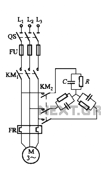
Single-speed motor excitation from the electrical braking circuit
The circuit illustrated in Figure 3-151 consists of capacitor banks arranged in a specific configuration. Figure 3-151 (a) depicts capacitor banks connected in a shaped configuration, which is suitable for shaped or Y-connected motors. Figure 3-151 (b) shows Y-connected capacitor...

Closed loop power control with a single speed
This is another example of a closed-loop speed control system. It utilizes a single voltage supply and an L298 integrated H-bridge power amplifier capable of handling 24V. Similar to the previous example, it is also suitable for two-way speed control.
The...
Single-speed motor excitation from the electrical braking circuit
The circuit illustrated in Figure 3-151 consists of capacitor banks arranged in a specific configuration. Figure 3-151 (a) depicts capacitor banks connected in a shaped configuration, which is suitable for shaped or Y-connected motors. Figure 3-151 (b) shows Y-connected capacitor...
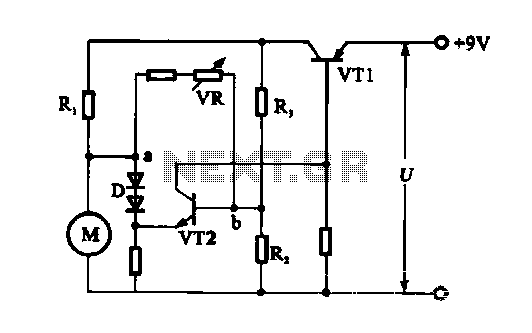
Electronic circuit steady speed motor application
The electronic circuit for steady speed motor applications utilizes an automatic remote control system to regulate the motor power supply, thereby achieving consistent speed control. The circuit diagram illustrates a DC motor connected to the system. Given that the DC...

Motor Y starting circuit shape
Motor windings are set to connect in a Y configuration while the load is active. The system includes an electric suction mechanism, and the motor is designed to operate under specific conditions. It is rated for 600 revolutions per minute...
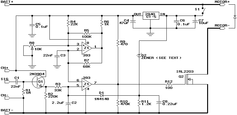
Build a Miniature High-Rate Speed Control with Battery Eliminator Circuit (BEC)
This design is based on a publication by Milan Lulic in the German magazine elektroModell. Lulic's design utilizes surface mount technology (SMT), while this version employs standard off-the-shelf components, making it more accessible for hobbyists. For those interested in a...
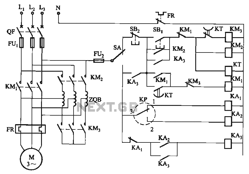
Electrical contacts Level IV controlled circuit
The circuit utilizes a motor auto-voltage transformer for starting.
The motor auto-voltage transformer start circuit is designed to provide a controlled method for initiating the operation of an electric motor. This type of circuit is particularly beneficial in applications where a...
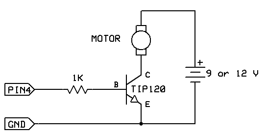
motor switch led circuit
The strategy involves assembling the circuit in stages, testing each component as it is integrated. Once all connections are established and can be controlled or read correctly by the computer, the main program can be developed with assurance that all...
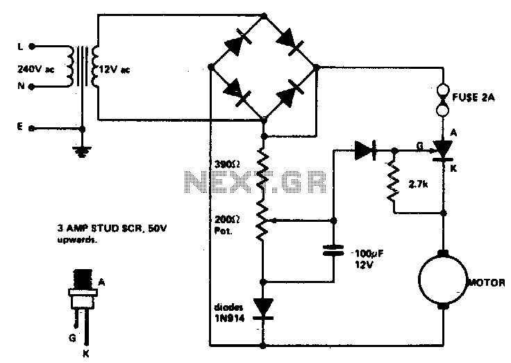
Speed control for model trains or cars
Low voltage speed control provides excellent starting torque and effective speed regulation. Additionally, a reversing switch can be integrated into the motor leads.
Low voltage speed control circuits are essential in applications where precise motor control is required, such as in...