


Fan motor driving circuit
#fan motor
#motor drive
#power circuit
#driving circuit
#control circuit
#electronics
#circuit design
#electrical engineering
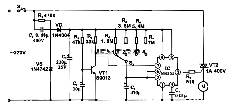
Description: The fan motor driving circuit is depicted as a basic configuration comprising a power circuit and a motor drive circuit. The power supply circuit primarily consists of a power switch (SI), a capacitor (C1), resistors (R1), a Zener diode (VZ), a rectifier diode (VD), and a filter capacitor (C2). The control circuit is mainly constructed from a transistor (VT1), a timing selector switch (S2), an integrated circuit (IC) such as the NE555, and associated peripheral components. An AC voltage of 22V is reduced by C1, rectified by VD, filtered, and regulated to provide a DC output voltage of approximately 12V. Upon powering on, capacitor C3 charges to a specific voltage level. Once this voltage reaches the predetermined threshold, VT1 conducts, causing the output pin of the integrated circuit IC to go low, which in turn activates R2 and powers the motor (M) to initiate rotation.
The fan motor driving circuit serves as an efficient mechanism for controlling a fan motor's operation. The power supply circuit is crucial for converting the incoming AC voltage into a usable DC voltage for the motor. The components involved in this conversion process include the power switch (SI), which allows for the control of power flow, and the capacitor (C1), which helps in smoothing out the voltage fluctuations. The Zener diode (VZ) plays a vital role in voltage regulation, ensuring that the output voltage remains stable at around 12V, which is essential for the reliable operation of the motor.
The rectifier diode (VD) is responsible for converting the AC voltage into DC, while the filter capacitor (C2) further smooths the output to eliminate any ripple. The control circuit, centered around the NE555 integrated circuit, is designed to manage the timing and operation of the fan motor. The timing selector switch (S2) allows for adjustments in the operation duration or speed of the fan, providing flexibility based on user requirements.
The charging behavior of capacitor C3 is critical in determining when the motor will start. As the circuit is powered, C3 charges until it reaches a specified voltage. At this point, the transistor (VT1) becomes conductive, which triggers the NE555 IC to change its output state. This change sends a signal to turn on resistor R2, thereby energizing the motor (M) and facilitating its rotation. The entire design emphasizes a balance between simplicity and functionality, making it suitable for various fan applications.Fan motor driving circuit Shown as a simple fan motor driving circuit, which is mainly from the power circuit, the motor drive circuit portion constituted. The power supply cir cuit mainly by the power switch SI, capacitor cJ, resistors Rl, Zener diode vs, rectifier diode VD and filter element capacitor C2 and the like; and a control circuit mainly by the transistor VTI, timing selector switch S2 test machine integration. circuit lC (NE555) and related peripheral element composition. AC 22V voltage through C1 buck, VD rectifier, q filter, vS regulated output DC voltage of about 12 V.
When the power is turned on, 1V to charge the capacitor C3, c3 ends when the voltage rises to the set value, VT1 conduction, the integrated circuit IC pin goes low, the pin output high, so rr2 turned on, the motor M is energized to rotate.
The fan motor driving circuit serves as an efficient mechanism for controlling a fan motor's operation. The power supply circuit is crucial for converting the incoming AC voltage into a usable DC voltage for the motor. The components involved in this conversion process include the power switch (SI), which allows for the control of power flow, and the capacitor (C1), which helps in smoothing out the voltage fluctuations. The Zener diode (VZ) plays a vital role in voltage regulation, ensuring that the output voltage remains stable at around 12V, which is essential for the reliable operation of the motor.
The rectifier diode (VD) is responsible for converting the AC voltage into DC, while the filter capacitor (C2) further smooths the output to eliminate any ripple. The control circuit, centered around the NE555 integrated circuit, is designed to manage the timing and operation of the fan motor. The timing selector switch (S2) allows for adjustments in the operation duration or speed of the fan, providing flexibility based on user requirements.
The charging behavior of capacitor C3 is critical in determining when the motor will start. As the circuit is powered, C3 charges until it reaches a specified voltage. At this point, the transistor (VT1) becomes conductive, which triggers the NE555 IC to change its output state. This change sends a signal to turn on resistor R2, thereby energizing the motor (M) and facilitating its rotation. The entire design emphasizes a balance between simplicity and functionality, making it suitable for various fan applications.Fan motor driving circuit Shown as a simple fan motor driving circuit, which is mainly from the power circuit, the motor drive circuit portion constituted. The power supply cir cuit mainly by the power switch SI, capacitor cJ, resistors Rl, Zener diode vs, rectifier diode VD and filter element capacitor C2 and the like; and a control circuit mainly by the transistor VTI, timing selector switch S2 test machine integration. circuit lC (NE555) and related peripheral element composition. AC 22V voltage through C1 buck, VD rectifier, q filter, vS regulated output DC voltage of about 12 V.
When the power is turned on, 1V to charge the capacitor C3, c3 ends when the voltage rises to the set value, VT1 conduction, the integrated circuit IC pin goes low, the pin output high, so rr2 turned on, the motor M is energized to rotate.
Electronic Projects
This program includes circuit design CAD, simulation, and auto-routing PC layout. PSPICE is also utilized at Unisys, which offers more capabilities but costs six times as much and requires annual renewal. With these requirements and others in mind, a variation...
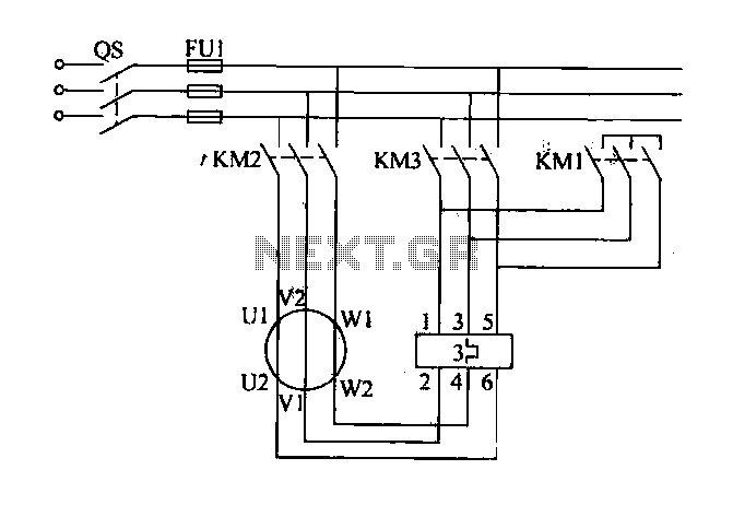
Fan motor starting circuit diagram
Traditional control methods for fan power equipment involve manual or relay control, which often leads to issues of poor reliability and flexibility. For instance, when the motor capacity is large, the startup process can be prolonged, resulting in high starting...
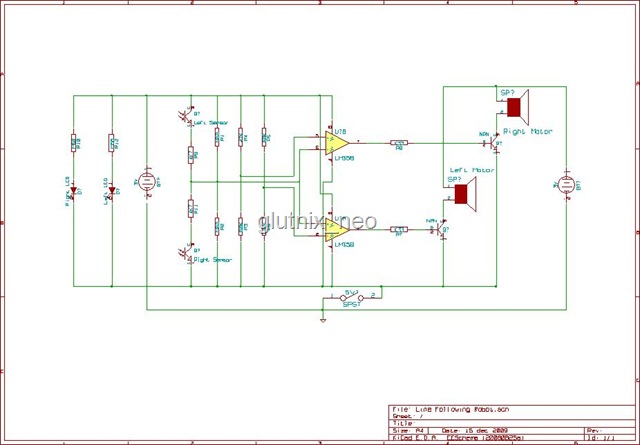
Simple MCU-less Differential Motor Drive Circuit
Originally, the tank cost around Php 400 but was later sold for approximately a hundred pesos less. Recognizing a great deal, the decision was made to purchase the toy. Opening the toy proved to be somewhat challenging. The track belt...
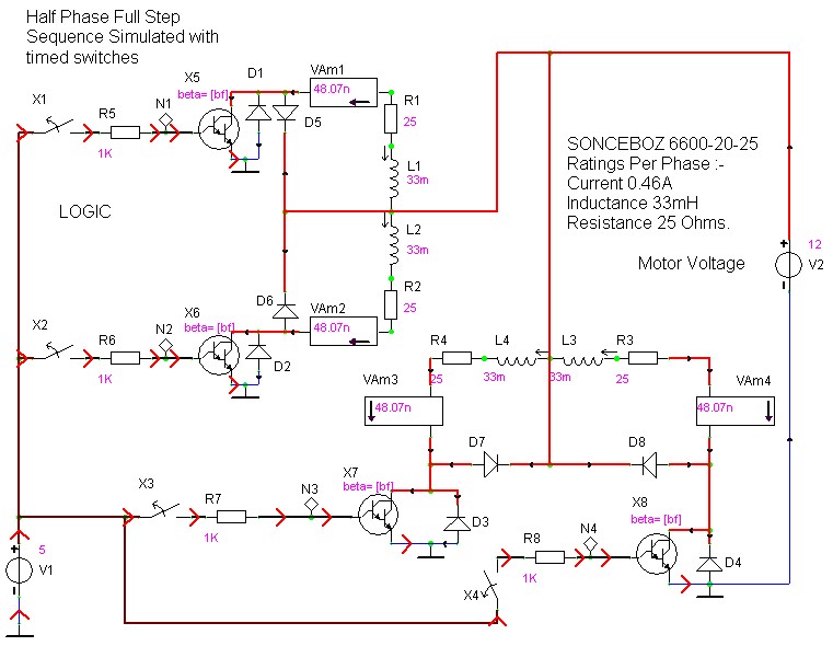
case stepper
Beige Bag Software has been offering affordable and innovative circuit design tools since 1990. B2 Spice provides schematics as well as analog, digital, and mixed-mode electronic circuit simulation. It integrates with EAGLE and CADSTAR PCB software.
B2 Spice is a powerful...
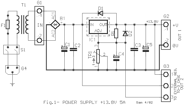
Electronics Projects Circuits
Over 1400 top electronics projects and electronic circuits with photos, datasheets, and easy-to-read schematics, along with explanations of how they work and how to build them.
The collection comprises a vast array of electronics projects suitable for enthusiasts and professionals alike....
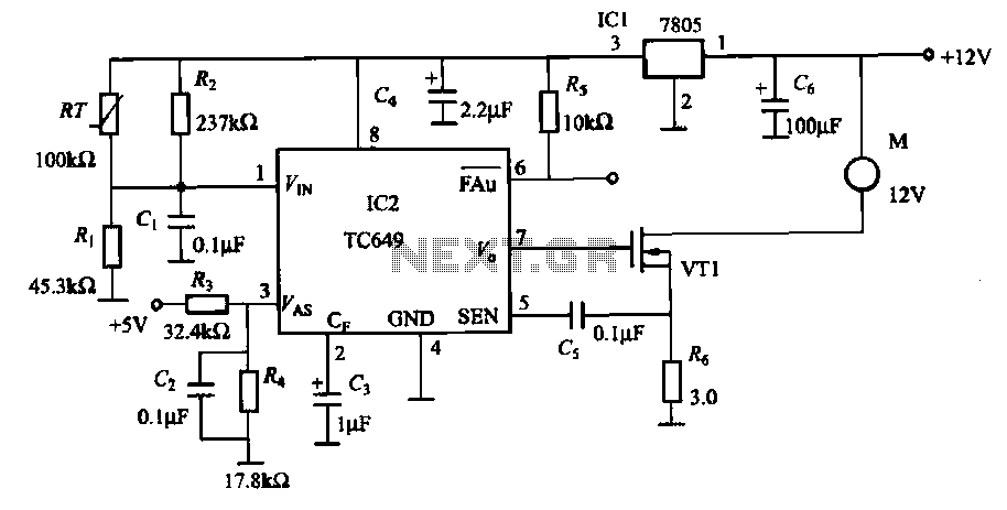
TC649 motor drive circuit with overheat protection
A motor is a heating device that can overheat, often due to accidents or overloads caused by excessive coil winding temperatures. The TC649 motor overheating protection and drive circuit, depicted in FIG. 1-9, utilizes an NTC thermistor (RT) positioned near...
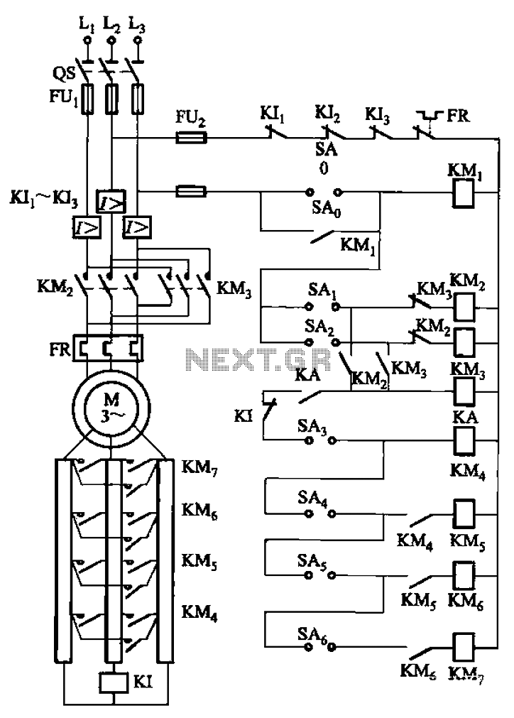
A control circuit reversing braking and reverse grading speed control function
The circuit depicted in Figure 3-168 utilizes a controller for speed grading and reversing control. A reverse brake is connected to the rotor circuit through an overcurrent relay, labeled KI, for control. The current relay KIi to KI3 serves as...