


Frequency sensitive rheostat manually start reversing circuit
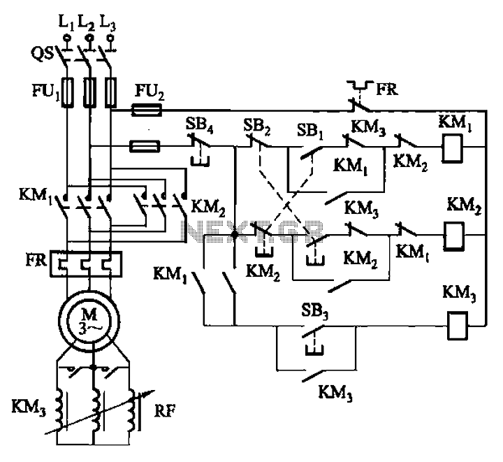
Description: The circuit illustrated in Figure 3-166 employs a button control mechanism. To initiate forward motion, the user presses button SB1, which activates the motor rotor through a frequency-sensitive rheostat (RF). As the motor speed approaches its rated speed, a brief press of button SB3 disables the RF operation. For reverse operation, the user presses button SB2 to start the process, which follows the same sequence as the forward motion.
The circuit operates by utilizing a motor control system that integrates a frequency-sensitive rheostat to manage the motor's speed effectively. The button controls (SB1, SB2, and SB3) provide a user-friendly interface for initiating forward and reverse operations. When SB1 is pressed, it sends a signal to the motor control circuitry, allowing current to flow through the frequency-sensitive rheostat (RF). This component adjusts the voltage applied to the motor, thereby controlling its rotational speed based on the frequency of the input signal.
As the motor accelerates and approaches its rated speed, the user can short press button SB3, which triggers a feedback mechanism that momentarily disengages the RF. This allows the motor to run at its rated speed without the additional resistance from the rheostat, optimizing performance and efficiency.
For reverse operations, button SB2 is utilized to initiate the same process as the forward motion. The circuit design ensures that both forward and reverse operations can be performed smoothly, with the ability to adjust speed dynamically based on user input. The inclusion of frequency-sensitive control allows for precise speed management, making this circuit suitable for applications requiring variable motor control. Overall, this circuit exemplifies a practical approach to motor control using simple button interfaces and responsive electronic components. Circuit shown in Figure 3-166. It uses the button control. When start forward, press SB], the motor rotor string frequency sensitive people rheostat RF operation. When the moto r speed increased to close to the rated speed, short press the button SB3, RF out of operation. Reverse start, press SB2 to startup process forward and start the same process.
The circuit operates by utilizing a motor control system that integrates a frequency-sensitive rheostat to manage the motor's speed effectively. The button controls (SB1, SB2, and SB3) provide a user-friendly interface for initiating forward and reverse operations. When SB1 is pressed, it sends a signal to the motor control circuitry, allowing current to flow through the frequency-sensitive rheostat (RF). This component adjusts the voltage applied to the motor, thereby controlling its rotational speed based on the frequency of the input signal.
As the motor accelerates and approaches its rated speed, the user can short press button SB3, which triggers a feedback mechanism that momentarily disengages the RF. This allows the motor to run at its rated speed without the additional resistance from the rheostat, optimizing performance and efficiency.
For reverse operations, button SB2 is utilized to initiate the same process as the forward motion. The circuit design ensures that both forward and reverse operations can be performed smoothly, with the ability to adjust speed dynamically based on user input. The inclusion of frequency-sensitive control allows for precise speed management, making this circuit suitable for applications requiring variable motor control. Overall, this circuit exemplifies a practical approach to motor control using simple button interfaces and responsive electronic components. Circuit shown in Figure 3-166. It uses the button control. When start forward, press SB], the motor rotor string frequency sensitive people rheostat RF operation. When the moto r speed increased to close to the rated speed, short press the button SB3, RF out of operation. Reverse start, press SB2 to startup process forward and start the same process.
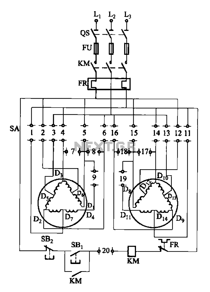
2Y-Y-2 - connection four-speed motor switch control circuit
The 3-119 circuit shown in the figure combines switch SA to realize the stator windings, specifically the 2, Y, and 2Y connections, which correspond to the motor speed n1.
The 3-119 circuit is designed to facilitate the control of motor speed...
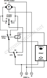
To Automate Rolling Shutter Motor
To automate the opening and closing of a rolling shutter using a time-controlled switch, additional wiring will be necessary.
To implement an automated system for a rolling shutter, a time-controlled switch can be utilized to manage the operation of the shutter....
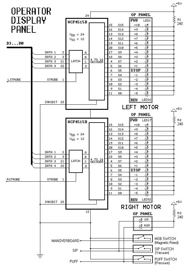
Dual-Motor SIP&PUFF Controlled Kayak System
The YouTube video below demonstrates the quick and easy setup of the system at the launch site.
The provided description indicates a focus on the efficiency of system installation at a launch site, as showcased in a YouTube video. In an...
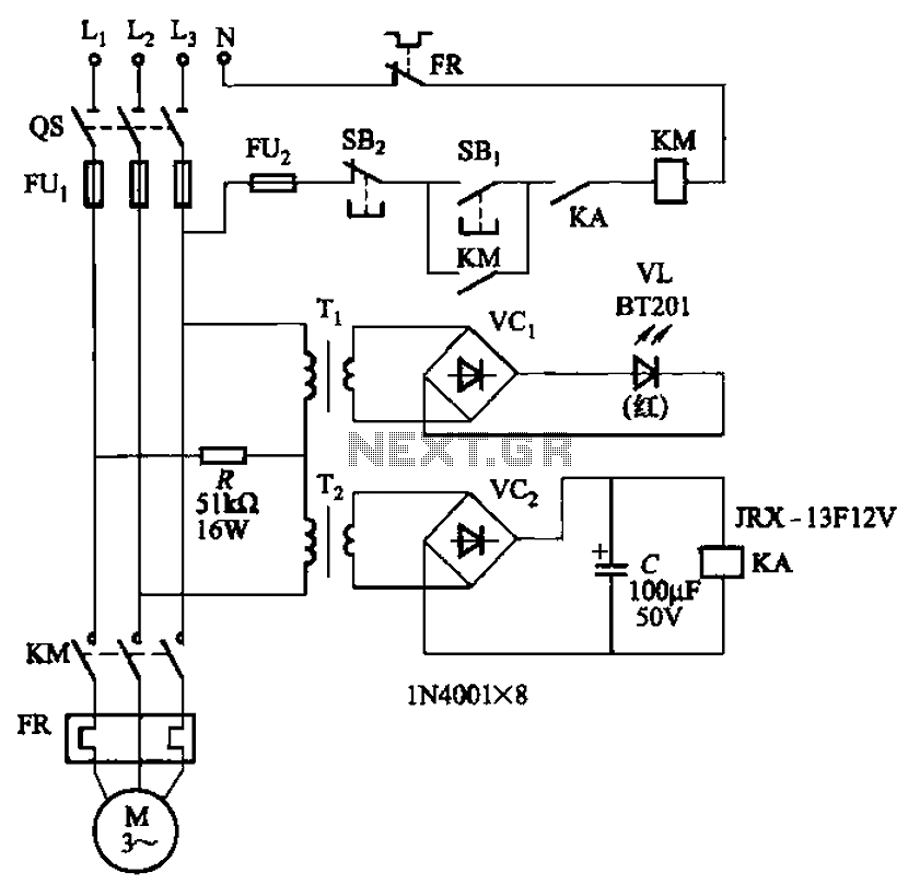
Allowing only one-way operation of the motor-controlled circuit 2
The circuit depicted in Figure 3-92 employs a dual-phase sequence protection relay for sensing. When the power supply exhibits a positive phase sequence (U, V, W), the relay KA is activated. If the power supply maintains the correct phase sequence,...

5-motor hexapod circuit
This circuit has a long history, originating from an idea by Rich Piotter and later refined by Wilf Rigter and Bruce Robinson. The final result does not include the necessary motor drivers, which are typically H-bridge based, but presents a...
2Y-Y-2 - connection four-speed motor switch control circuit
The 3-119 circuit shown in the figure combines switch SA to realize the stator windings, specifically the 2, Y, and 2Y connections, which correspond to the motor speed n1.
The 3-119 circuit is designed to facilitate the control of motor speed...
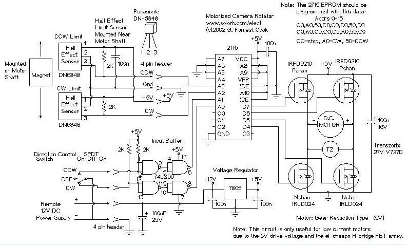
Motorized Video Camera Mount
The camera rotator circuit utilizes a 2716 EPROM to store a logic value table that governs the motor driver (H-bridge) circuit. The schematic illustrates the EPROM data. By employing the EPROM, a significant number of discrete gates are eliminated. The...
Gray Projects
After learning to operate the device, it became evident that inertia posed a significant challenge. The constructed system is notably heavy, making it difficult to initiate motor operation at full speed. Despite having some understanding of physics, practical experience is...
Motorized Video Camera Mount
The camera rotator circuit utilizes a 2716 EPROM to store a logic value table that governs the motor driver (H-bridge) circuit. The schematic illustrates the EPROM data. By employing the EPROM, a significant number of discrete gates are eliminated. The...