


h bridge How can I implement regenerative braking of a DC motor
#H-bridge
#DC motor
#regenerative braking
#PWM
#energy conversion
#battery storage
#half-bridge
#motor driver
#electric vehicles
#braking system
Description: Many electric vehicles can convert the momentum of the car into stored energy in batteries, instead of dissipating it as heat in the brake pads. This process is known as regenerative braking. It can be implemented using a motor controlled by a half-bridge or H-bridge configuration with PWM (Pulse Width Modulation) or similar techniques. For this analysis, a half-bridge configuration will be considered.
In a non-regenerative braking scenario, when the bridge output is high (S1 closed, S2 open), the motor accelerates to full speed. If the bridge is switched to a low state, the motor does not simply coast to a stop; it abruptly halts as if a brake has been applied. This occurs because a motor can be modeled as a series inductor and a voltage source. The torque produced by the motor is proportional to the current flowing through it. The voltage source, referred to as back-EMF, is proportional to the motor's speed. Consequently, a motor draws more current when under load or stalled, as decreased speed results in reduced back-EMF, which opposes the supply voltage less, leading to increased current draw.
When the motor is running at high speed, the back-EMF is nearly equal to the supply voltage minus the voltage drop across the resistance (R1). In this state, minimal current flows due to back-EMF countering most of the supply voltage. Upon switching the bridge to the low side, the inductor (L1) initially prevents an immediate change in current. However, after a brief time defined by the time constant of L1/R1, the back-EMF reverses the current direction, resulting in a significant current flowing in the opposite direction. This reversed current generates torque in the opposite direction, decelerating the mechanical load rapidly. As the motor speed decreases, so does the back-EMF and the resulting current, ultimately bringing the load to a stop.
During this process, a substantial amount of power is dissipated as heat in the motor's winding resistance and the H-bridge transistors. The current generated by the back-EMF can approach the stall current of the motor; hence, if the motor can operate stalled without overheating, it can effectively perform regenerative braking continuously. However, if the system remains in this state for too long, the current direction may reverse, leading to battery discharge and motor acceleration instead of braking.
To maintain effective regenerative braking, it is crucial to switch back to the state where the back-EMF can build current again, allowing for energy transfer into the battery. This cycle should be repeated quickly to maximize energy recovery. When using PWM to drive the motor, the inductance (L1) acts as a flywheel, averaging the applied voltage. For example, with a supply voltage of 10V and a PWM duty cycle of 80%, the effective voltage applied to the motor is averaged, allowing for smoother operation and effective energy recovery during regenerative braking.
The implementation of regenerative braking in electric vehicles not only enhances energy efficiency but also extends the range of electric vehicles by allowing the recovery of kinetic energy during deceleration.Many electric cars are able to convert the momentum of the car into stored energy in batteries, rather than convert it to useless heat at the brake pads. How does this work How can I implement it myself Probably you already have it, and just didn`t know it.
If you are driving a motor with a half-bridge or H-bridge and PWM or similar, you have regenerative braking. Let`s consider a half-bridge, since for this analysis we will run the motor in only one direction: First, let`s consider non-regenerative braking. If the bridge output is high (S1 closed, S2 open), the motor will accelerate to full speed. If the bridge is now switched low, the motor won`t just gently coast to a stop. It will slam to a stop, as if someone but a brake on it. Why A motor can be modelled as a series inductor and voltage source. The motor torque is proportional to current. The voltage source is called back-EMF, and it`s proportional to the speed of the motor. This is why a motor draws more current when it is loaded (or worst, stalled): with the speed decreased, the back-EMF is decreased, and it opposes the supply voltage less, resulting in higher current. Let`s redraw our schematic with that model, with values as if our motor is spinning at high speed: This motor is running at full speed.
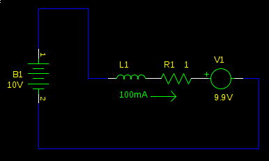
We have a small current to overcome the friction in the motor, and the back-EMF is the supply voltage, less the voltage drop over R1. Not much current flows because the back-EMF cancels most of the supply voltage, so L1 and R1 see only 100mV.
Now what happens when we switch the bridge to the low side At first, nothing. L1 prevents an immediate change in current. However, this doesn`t last long, and very soon (defined by the time constant of $L_1 / R_1$, not more than a couple $ms$ typically) the back-emf (V1) has reversed the current, and now it`s going in the other direction. It`s also pretty huge, since now L1 and R1 don`t see the small difference of $V_{B1}-V_1$ (it was $100mV$), but now they see the full 9.
9V from V1 alone: We now have a large current flowing in the opposite direction. Torque is proportional to current, so now instead of applying a gentle clockwise force, just enough to overcome friction, we are applying a hard counterclockwise force, and the mechanical load is rapidly decelerated. As the speed of the motor decreases, so does V1, and consequently so does the current, and the torque with it, until the load is no longer spinning.
Right. If you look at the circuit again, we have 99A flowing through R1. $P_{R1} = (99A)2 1Omega = 980. 1W$. The kinetic energy of the load was converted into heat in the motor`s winding resistance (and in a practical circuit, also the H-bridge transistors). Some motors will be destroyed by this high power. Others may not. The current generated by the back-EMF is about as strong as the stall current of the motor, so if your motor can run stalled without overheating, it can brake like this all day.
Ah ha! We are charging the battery! Of course, if we stay like this very long (again, defined by time constant $L_1 / R_1$) then the current direction will reverse, and we will be uncharging our battery, and accelerating our motor, not braking it. So don`t do that. As long as we remain in this state, the current is decreasing. So, we switch back to the other state, with the bridge low, so the back-emf can build the current back up.
Then we switch again, and shoot some of it into the battery. Repeat, fast. Once you understand the principle of operation, you can make some simplifications. When a motor is being driven by PWM, the inductance of the motor (L1) works like a flywheel, averaging the voltage you apply to the motor. It`s as if you had a real flywheel, and spun it by striking it with a hammer repeatedly. So in this example our supply voltage is 10V. If our PWM duty cycle is 80%, we are effectively d
In a non-regenerative braking scenario, when the bridge output is high (S1 closed, S2 open), the motor accelerates to full speed. If the bridge is switched to a low state, the motor does not simply coast to a stop; it abruptly halts as if a brake has been applied. This occurs because a motor can be modeled as a series inductor and a voltage source. The torque produced by the motor is proportional to the current flowing through it. The voltage source, referred to as back-EMF, is proportional to the motor's speed. Consequently, a motor draws more current when under load or stalled, as decreased speed results in reduced back-EMF, which opposes the supply voltage less, leading to increased current draw.
When the motor is running at high speed, the back-EMF is nearly equal to the supply voltage minus the voltage drop across the resistance (R1). In this state, minimal current flows due to back-EMF countering most of the supply voltage. Upon switching the bridge to the low side, the inductor (L1) initially prevents an immediate change in current. However, after a brief time defined by the time constant of L1/R1, the back-EMF reverses the current direction, resulting in a significant current flowing in the opposite direction. This reversed current generates torque in the opposite direction, decelerating the mechanical load rapidly. As the motor speed decreases, so does the back-EMF and the resulting current, ultimately bringing the load to a stop.
During this process, a substantial amount of power is dissipated as heat in the motor's winding resistance and the H-bridge transistors. The current generated by the back-EMF can approach the stall current of the motor; hence, if the motor can operate stalled without overheating, it can effectively perform regenerative braking continuously. However, if the system remains in this state for too long, the current direction may reverse, leading to battery discharge and motor acceleration instead of braking.
To maintain effective regenerative braking, it is crucial to switch back to the state where the back-EMF can build current again, allowing for energy transfer into the battery. This cycle should be repeated quickly to maximize energy recovery. When using PWM to drive the motor, the inductance (L1) acts as a flywheel, averaging the applied voltage. For example, with a supply voltage of 10V and a PWM duty cycle of 80%, the effective voltage applied to the motor is averaged, allowing for smoother operation and effective energy recovery during regenerative braking.
The implementation of regenerative braking in electric vehicles not only enhances energy efficiency but also extends the range of electric vehicles by allowing the recovery of kinetic energy during deceleration.Many electric cars are able to convert the momentum of the car into stored energy in batteries, rather than convert it to useless heat at the brake pads. How does this work How can I implement it myself Probably you already have it, and just didn`t know it.
If you are driving a motor with a half-bridge or H-bridge and PWM or similar, you have regenerative braking. Let`s consider a half-bridge, since for this analysis we will run the motor in only one direction: First, let`s consider non-regenerative braking. If the bridge output is high (S1 closed, S2 open), the motor will accelerate to full speed. If the bridge is now switched low, the motor won`t just gently coast to a stop. It will slam to a stop, as if someone but a brake on it. Why A motor can be modelled as a series inductor and voltage source. The motor torque is proportional to current. The voltage source is called back-EMF, and it`s proportional to the speed of the motor. This is why a motor draws more current when it is loaded (or worst, stalled): with the speed decreased, the back-EMF is decreased, and it opposes the supply voltage less, resulting in higher current. Let`s redraw our schematic with that model, with values as if our motor is spinning at high speed: This motor is running at full speed.
We have a small current to overcome the friction in the motor, and the back-EMF is the supply voltage, less the voltage drop over R1. Not much current flows because the back-EMF cancels most of the supply voltage, so L1 and R1 see only 100mV.
Now what happens when we switch the bridge to the low side At first, nothing. L1 prevents an immediate change in current. However, this doesn`t last long, and very soon (defined by the time constant of $L_1 / R_1$, not more than a couple $ms$ typically) the back-emf (V1) has reversed the current, and now it`s going in the other direction. It`s also pretty huge, since now L1 and R1 don`t see the small difference of $V_{B1}-V_1$ (it was $100mV$), but now they see the full 9.
9V from V1 alone: We now have a large current flowing in the opposite direction. Torque is proportional to current, so now instead of applying a gentle clockwise force, just enough to overcome friction, we are applying a hard counterclockwise force, and the mechanical load is rapidly decelerated. As the speed of the motor decreases, so does V1, and consequently so does the current, and the torque with it, until the load is no longer spinning.
Right. If you look at the circuit again, we have 99A flowing through R1. $P_{R1} = (99A)2 1Omega = 980. 1W$. The kinetic energy of the load was converted into heat in the motor`s winding resistance (and in a practical circuit, also the H-bridge transistors). Some motors will be destroyed by this high power. Others may not. The current generated by the back-EMF is about as strong as the stall current of the motor, so if your motor can run stalled without overheating, it can brake like this all day.
Ah ha! We are charging the battery! Of course, if we stay like this very long (again, defined by time constant $L_1 / R_1$) then the current direction will reverse, and we will be uncharging our battery, and accelerating our motor, not braking it. So don`t do that. As long as we remain in this state, the current is decreasing. So, we switch back to the other state, with the bridge low, so the back-emf can build the current back up.
Then we switch again, and shoot some of it into the battery. Repeat, fast. Once you understand the principle of operation, you can make some simplifications. When a motor is being driven by PWM, the inductance of the motor (L1) works like a flywheel, averaging the voltage you apply to the motor. It`s as if you had a real flywheel, and spun it by striking it with a hammer repeatedly. So in this example our supply voltage is 10V. If our PWM duty cycle is 80%, we are effectively d
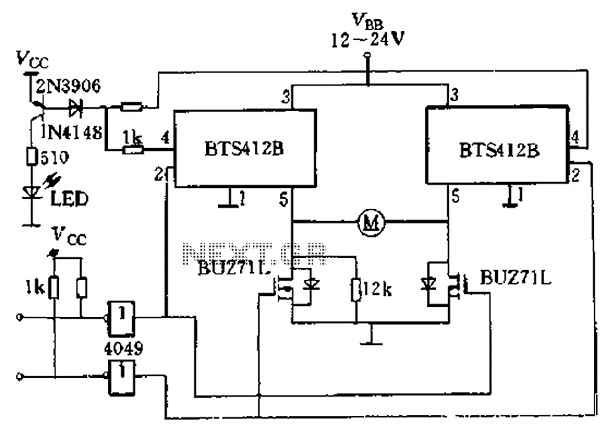
H-bridge driver circuit composed by the Smart SIPMOS
The BTS412B functions as two high-side power MOSFET switches, while two BU271L (50V, Zhang 1n) serve as low-side switches, forming a bi-directional H-bridge DC motor drive circuit. This configuration is designed for electrical automatic door systems, capable of handling continuous...
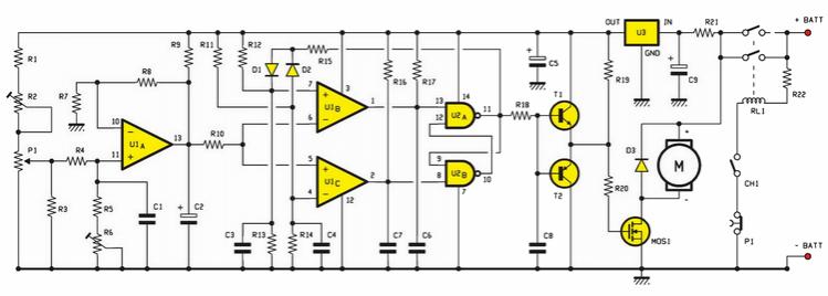
PWM circuit
An electric scooter and E-Bike PWM speed controller circuit has been constructed. However, the oscillator is not functioning as intended. The printed circuit board has been checked and is confirmed to be in good condition, including all resistors.
The electric scooter...
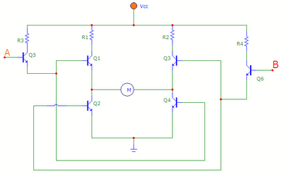
H-bridge circuit using NPN transistors
The transistors Q1, Q2, Q3, and Q4 form a bridge circuit. These are typically power transistors designed to handle high current. Transistors Q5 and Q6 drive the bridge. When input A is set high and input B is set low,...
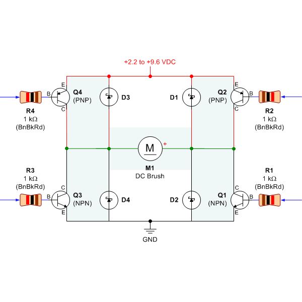
the dc motor circuit
Selecting the appropriate DC motor is essential for constructing mobile robots. Testing DC motors is straightforward and can be accomplished by assembling a basic DC motor circuit. The components needed for this circuit include a DC motor, a battery power...
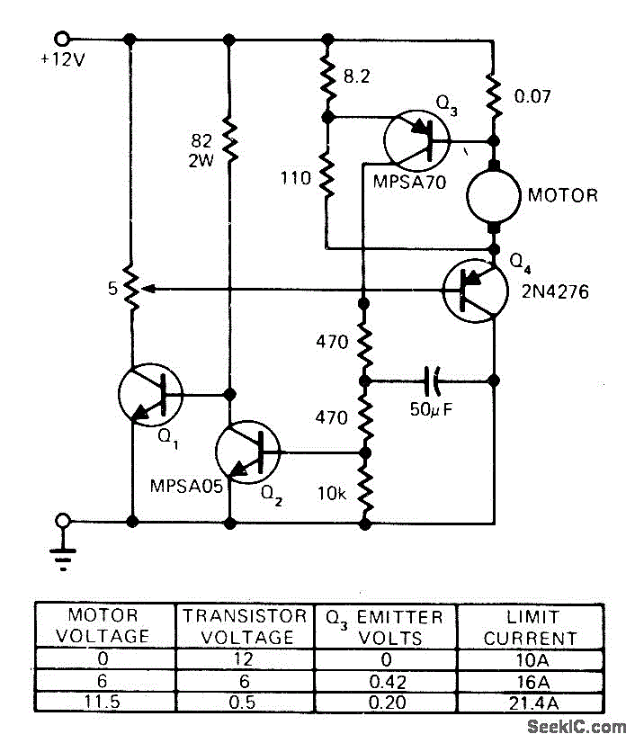
STALLED_MOTOR_PROTECTION
The modification of a basic speed control circuit for small DC permanent-magnet motors implements a maximum current limit during normal operating conditions and a reduced current limit during stall conditions. This design aims to limit the dissipation of series transistor...
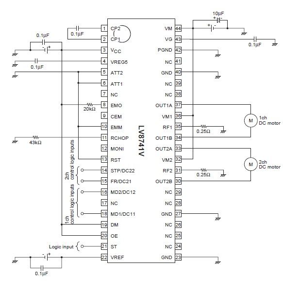
LV8741V PWM stepping motor driver electronic project circuit design
The circuit diagram illustrates an electronic project that requires a few external electronic components. The PWM current-control stepping motor driver IC can provide a maximum output current of up to 1.5 amperes. The configuration settings for the PWM current-control DC...
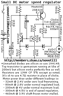
Small DC Motor Speed Regulator
Reverse engineered circuit diagram of a motor speed regulator out of a portable pocket tape recorder containing a single motor for all functions. This circuit works amazingly well, keeping the motor speed constant regardless of shaft load and battery voltage.
The...
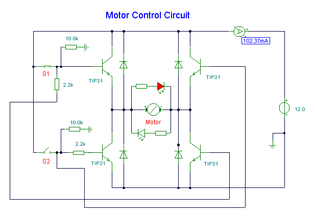
dc motor control circuit
S1 and S2 are normally open, push-to-close, momentary switches. The diodes can be red or green and serve solely as indicators for direction. The TIP31 transistors may need to be adjusted based on the motor specifications. It is important to...
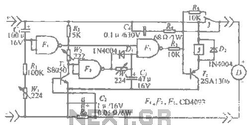
A high-power DC motor overcurrent protection circuit
The "R-h sampling circuit limit order" aims to reduce the sampling resistor. A DC voltage level can be positioned between the components. The circuit includes a line amplifier that allows for magnification adjustments and is designed to protect against current...