


Homebrew Fan Speed Controller
#fan speed controller
#temperature control
#PWM
#computer fans
#LED indicator
#manual control
#automatic control
#cooling system
#DIY
#homebrew
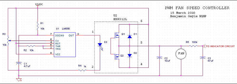
Description: A fan speed controller for computer fans consists of two sections: one for manual speed control and another for automatic temperature-dependent speed control. Additionally, there is a section for a simple LED output indicator. While it is common to run fans directly from motherboard connectors, some fans, like the Vantec Tornado, require more current than the motherboard can provide. This necessitates an external controller to adjust the speed. Some users prefer the tactile experience of manual knobs. This project is intended for those who enjoy hands-on electronics and have some familiarity with building circuits from scratch. It is advisable to breadboard and test circuits before soldering. The manual speed control utilizes a potentiometer to adjust the voltage at the base of a transistor, which acts as a voltage follower and current amplifier (up to 3A with TIP41C transistors). An output capacitor aids in starting the fan at lower voltages and reduces motor noise. The automatic speed control circuit replaces the potentiometer with an NTC thermistor connected to an op-amp, which varies the fan speed based on temperature. The thermistor's resistance decreases with rising temperatures, altering the input voltage to the op-amp. The output of the op-amp is connected to a transistor that drives the fans, functioning as a difference amplifier with negative feedback. As temperature increases, the fan speed increases to help lower the temperature.
A fan speed controller circuit typically includes three main components: a manual control section, an automatic control section, and an LED indicator. The manual control section employs a potentiometer to adjust the voltage at the base of a transistor, allowing users to set the fan speed directly. The transistor, configured as a voltage follower, enables a small input current to control a larger output current, effectively allowing the circuit to handle higher loads such as those required by high-performance fans.
The automatic control section utilizes an NTC thermistor to monitor temperature changes. The thermistor is part of a voltage divider, where its resistance decreases as the temperature rises. This change in resistance alters the voltage at the inverting input of an operational amplifier (op-amp). The non-inverting input receives a reference voltage set by another potentiometer, establishing a threshold for minimum fan speed. The op-amp functions as a difference amplifier, outputting a voltage that corresponds to the difference between the two inputs. This output controls a transistor that drives the power transistor, which in turn powers the fans.
The circuit design incorporates a capacitor at the output, which serves a dual purpose: it helps the fans start at lower voltages and acts as a low-pass filter to minimize electrical noise generated by the fan motors. The entire circuit can be assembled on a perfboard using wire-wrap or point-to-point techniques, allowing for flexibility in construction. It is recommended to bench-test the circuit thoroughly before installation to ensure functionality and reliability. This project caters to enthusiasts who prefer a customized solution over commercial fan controllers, providing an engaging experience in electronics assembly and design.A fan speed controller for your computer fans. There are two sections: one for manual speed control, and one for automatic (temperature dependent) speed control. There is also a third section for a simple LED output indicator. Why not just run the fans off the motherboard fan connectors This is what most people should do. However, there are fans out there such as the Vantec Tornado which require more current than the motherboard will supply. This requires an external controller to vary the speed. Some people just want the extra knobs to turn. Why not just buy a fan controller and plug-n-play That is what most people should do. This article is for those who like to tinker and play and burn themselves with soldering irons. It is nice to end up with a working project that you can point to and say "I built that". These projects assume that the reader is somewhat familiar with electronics and has the ability to build circuits from scratch. My projects were built with parts and materials on hand, your available parts and materials may vary.
Breadboarding and testing the circuits before soldering is strongly advised. In case you don`t know what I`m talking about, here is a pic of the automatic speed control circuit breadboarded and under test on the bench: Always bench-test the finished project before installing it in your computer to make sure it works and works like it is supposed to. Use whatever construction method suits you best. These projects worked out well for me using a mix of wire-wrap and point-to-point on perfboard. Do not assume that the way I went about these circuits is the only or best way, there are other ways to accomplish the same thing (please post and discuss The simplest approach is to manually adjust the speed by turning a knob.
This circuit uses a potentiometer to vary the voltage at the base of a transistor, which acts as a voltage follower: the output voltage follows the input voltage. This also acts as a current amplifier, as a small input current at the base is translated to a large input current at the output (up to 3A with the TIP41C transistors I used on this project).
A capacitor on the output helps to start the fan at lower voltages, and acts as a low-pass filter to keep fan motor noise from propagating back into the power supply. This project is for those of you who, like me, are too lazy to be bothered to monitor your system temperature and turn the fan speed up when the temperature goes up.
This circuit takes the manual speed controller from above and replaces the potentiometer with an automatic control circuit. The temperature monitoring is done with a NTC thermistor connected to the inverting input of an op-amp.
"NTC" means that as the temperature increases, the resistance decreases. The thermistor is connected in a voltage divider, so that as its resistance changes, the voltage at the input of the op-amp changes. The non-inverting input is connected to a potentiometer to set the reference voltage, which effectively sets the lower limit on the fan speed.
The output voltage follows the difference in voltage at the two inputs. The output is connected to a small transistor which is darlington-connected to a power transistor that acts as a current amplifier, which drives the fans. This circuit is a difference amplifier with negative feedback. As temperature increases, the difference in voltage between the op-amp`s inputs increases. This causes the op-amp`s output voltage to increase, causing the transistor output voltage to increase.
This makes the fans spin faster, which hopefully results in the temperature decreasing. As th
A fan speed controller circuit typically includes three main components: a manual control section, an automatic control section, and an LED indicator. The manual control section employs a potentiometer to adjust the voltage at the base of a transistor, allowing users to set the fan speed directly. The transistor, configured as a voltage follower, enables a small input current to control a larger output current, effectively allowing the circuit to handle higher loads such as those required by high-performance fans.
The automatic control section utilizes an NTC thermistor to monitor temperature changes. The thermistor is part of a voltage divider, where its resistance decreases as the temperature rises. This change in resistance alters the voltage at the inverting input of an operational amplifier (op-amp). The non-inverting input receives a reference voltage set by another potentiometer, establishing a threshold for minimum fan speed. The op-amp functions as a difference amplifier, outputting a voltage that corresponds to the difference between the two inputs. This output controls a transistor that drives the power transistor, which in turn powers the fans.
The circuit design incorporates a capacitor at the output, which serves a dual purpose: it helps the fans start at lower voltages and acts as a low-pass filter to minimize electrical noise generated by the fan motors. The entire circuit can be assembled on a perfboard using wire-wrap or point-to-point techniques, allowing for flexibility in construction. It is recommended to bench-test the circuit thoroughly before installation to ensure functionality and reliability. This project caters to enthusiasts who prefer a customized solution over commercial fan controllers, providing an engaging experience in electronics assembly and design.A fan speed controller for your computer fans. There are two sections: one for manual speed control, and one for automatic (temperature dependent) speed control. There is also a third section for a simple LED output indicator. Why not just run the fans off the motherboard fan connectors This is what most people should do. However, there are fans out there such as the Vantec Tornado which require more current than the motherboard will supply. This requires an external controller to vary the speed. Some people just want the extra knobs to turn. Why not just buy a fan controller and plug-n-play That is what most people should do. This article is for those who like to tinker and play and burn themselves with soldering irons. It is nice to end up with a working project that you can point to and say "I built that". These projects assume that the reader is somewhat familiar with electronics and has the ability to build circuits from scratch. My projects were built with parts and materials on hand, your available parts and materials may vary.
Breadboarding and testing the circuits before soldering is strongly advised. In case you don`t know what I`m talking about, here is a pic of the automatic speed control circuit breadboarded and under test on the bench: Always bench-test the finished project before installing it in your computer to make sure it works and works like it is supposed to. Use whatever construction method suits you best. These projects worked out well for me using a mix of wire-wrap and point-to-point on perfboard. Do not assume that the way I went about these circuits is the only or best way, there are other ways to accomplish the same thing (please post and discuss The simplest approach is to manually adjust the speed by turning a knob.
This circuit uses a potentiometer to vary the voltage at the base of a transistor, which acts as a voltage follower: the output voltage follows the input voltage. This also acts as a current amplifier, as a small input current at the base is translated to a large input current at the output (up to 3A with the TIP41C transistors I used on this project).
A capacitor on the output helps to start the fan at lower voltages, and acts as a low-pass filter to keep fan motor noise from propagating back into the power supply. This project is for those of you who, like me, are too lazy to be bothered to monitor your system temperature and turn the fan speed up when the temperature goes up.
This circuit takes the manual speed controller from above and replaces the potentiometer with an automatic control circuit. The temperature monitoring is done with a NTC thermistor connected to the inverting input of an op-amp.
"NTC" means that as the temperature increases, the resistance decreases. The thermistor is connected in a voltage divider, so that as its resistance changes, the voltage at the input of the op-amp changes. The non-inverting input is connected to a potentiometer to set the reference voltage, which effectively sets the lower limit on the fan speed.
The output voltage follows the difference in voltage at the two inputs. The output is connected to a small transistor which is darlington-connected to a power transistor that acts as a current amplifier, which drives the fans. This circuit is a difference amplifier with negative feedback. As temperature increases, the difference in voltage between the op-amp`s inputs increases. This causes the op-amp`s output voltage to increase, causing the transistor output voltage to increase.
This makes the fans spin faster, which hopefully results in the temperature decreasing. As th
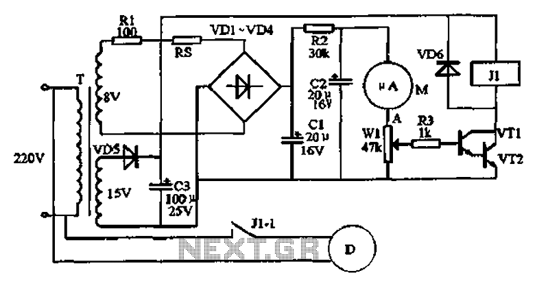
Temperature controller circuit
An automatic humidifier can be utilized for humidity control in households, hatcheries, poultry farms, or juvenile poultry houses. When the humidity level falls below 50%, the automatic humidifier activates to maintain a specific humidity level that is beneficial for both...
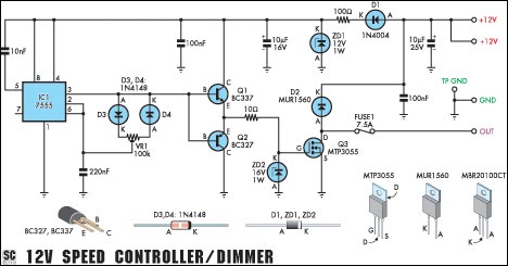
12V Speed Controller/Dimmer
This circuit serves as a speed controller for a 12V motor with a continuous rating of up to 5A or as a dimmer for a 12V halogen or standard incandescent lamp rated up to 50W. It regulates power to the...
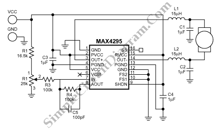
PWM Motor Speed Control Using Class D Audio Amplifier
This is a Class D audio amplifier circuit used to control the PWM motor speed. This circuit has two advantages for battery-powered portable devices. First, it provides high efficiency, which extends battery life.
The Class D audio amplifier operates by modulating...
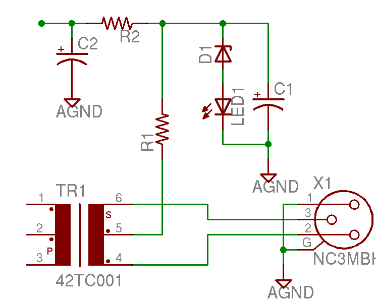
Help with a schematic please
A project is underway to construct the CountryHick DI as illustrated on DIYFactory, incorporating a few minor modifications. The final design aims to be a 1U unit with four inputs.
The CountryHick DI (Direct Injection) box is a crucial tool in...
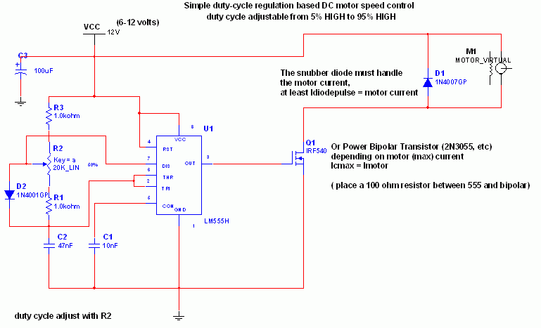
Simple DC motor PWM speed control
The 555 IC is configured as an astable multivibrator, producing a constant frequency independent of the duty cycle. The total resistance (R_charge + R_discharge, with the diode in consideration) remains constant at 22 kΩ, resulting in a frequency of approximately...
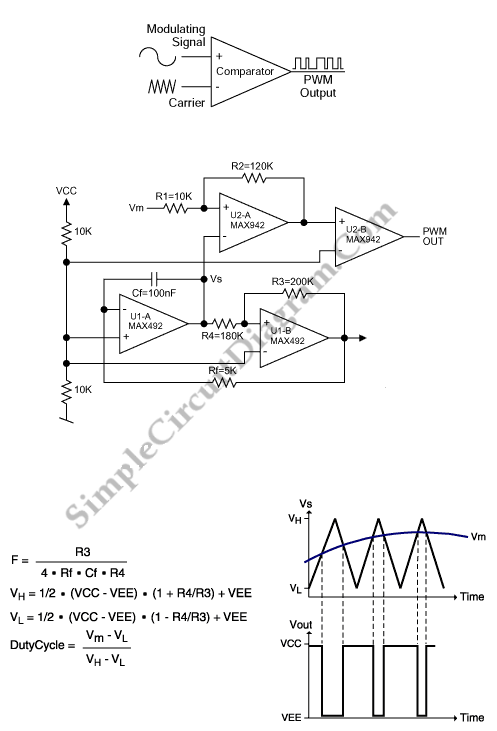
PWM Modulator Using Op-Amp
This is a simple PWM modulator circuit. Comparing the message signal to a ramp or triangular waveform is the simplest way to produce a PWM signal. When the...
The PWM (Pulse Width Modulation) modulator circuit operates by comparing a modulating signal,...
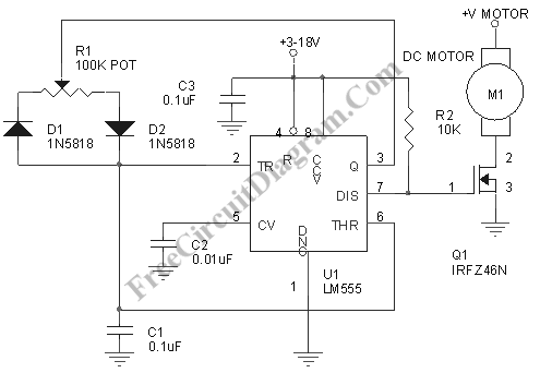
Motor Speed Control Using PWM
Pulse width modulation, commonly referred to as PWM, is utilized to regulate the power supplied to a load without sacrificing efficiency. This technique is often employed in controlling the speed of an electric motor.
PWM operates by varying the width of...
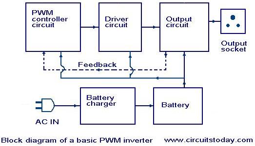
Introduction to PWM Inverters
Nowadays, most inverters available in the market utilize Pulse Width Modulation (PWM) technology. Inverters based on PWM technology exhibit superior performance in several aspects compared to those designed using conventional methods. These PWM inverters typically employ MOSFETs in the output...
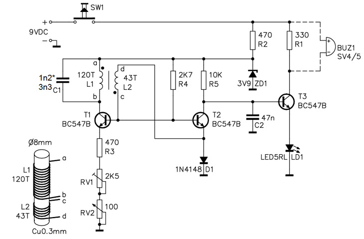
Homemade Metal Detector Kit
A simple home project can quickly become problematic if it encounters electric cables, gas, or water pipes, or the central heating system. Using a metal detector allows one to check for metal objects within walls, ceilings, or floors beforehand. An...