


How to connect a pulled motor from a printer to Breadboard and control with raspberry pi
#raspberry pi
#breadboard
#printer motor
#DC motor
#stepper motor
#motor control
#cobbler kit
#salvage
#DIY
#electronics
Description: A couple of motors were salvaged from an old printer, and there is uncertainty regarding how to connect them to a breadboard and subsequently to a Raspberry Pi. A cobbler kit for the Raspberry Pi is available for this purpose. Additionally, there is uncertainty about the type of motor, whether it is a DC motor or a stepper motor.
To connect the salvaged motors to a breadboard and interface them with a Raspberry Pi, it is essential to first identify the type of motors. If the motors are DC motors, they will typically have two terminals and can be driven using a simple H-bridge circuit for direction control and PWM (Pulse Width Modulation) for speed control. On the other hand, if the motors are stepper motors, they will have multiple terminals, usually four, six, or eight, depending on the type of stepper motor.
For a DC motor setup, the following components are typically required:
1. H-Bridge Motor Driver: This component allows for the control of the motor's direction and speed. Common H-bridge ICs include the L298N or L293D.
2. Power Supply: Ensure that the power supply voltage matches the motor specifications.
3. Raspberry Pi GPIO Pins: These pins will be used to send control signals to the H-bridge.
4. Breadboard: For easy connections and prototyping.
The connection process involves:
- Connecting the motor terminals to the output pins of the H-bridge.
- Connecting the H-bridge inputs to the Raspberry Pi GPIO pins.
- Providing power to the H-bridge from an appropriate external power source.
- Using the Raspberry Pi's GPIO library to control the motor through the H-bridge.
For a stepper motor setup, a stepper motor driver, such as the A4988 or DRV8825, is recommended. The stepper motor driver will simplify the control of the stepper motor by managing the sequence of signals required to rotate the motor. The connection process includes:
- Connecting the stepper motor wires to the driver according to the motor's wiring configuration.
- Connecting the driver to the Raspberry Pi GPIO pins for step and direction control.
- Providing adequate power to the stepper motor driver from an external power source.
In both cases, it is advisable to consult the datasheets for the specific motors and drivers to ensure proper connections and configurations. Additionally, programming the Raspberry Pi to control the motors can be accomplished using Python with libraries such as RPi.GPIO or gpiozero. This will allow for precise control over motor movements and functionalities.I managed to salvage a couple of motors from a worn down old printer, and I`m unsure of how to get about connecting it to a breadboard and then to a Raspberry Pi. I`ve got a cobbler kit for my Pi that allows me to connect it up to the breadboard. I`m also unsure about what kind of motor it is, DC or Stepper. The motor looks like:
To connect the salvaged motors to a breadboard and interface them with a Raspberry Pi, it is essential to first identify the type of motors. If the motors are DC motors, they will typically have two terminals and can be driven using a simple H-bridge circuit for direction control and PWM (Pulse Width Modulation) for speed control. On the other hand, if the motors are stepper motors, they will have multiple terminals, usually four, six, or eight, depending on the type of stepper motor.
For a DC motor setup, the following components are typically required:
1. H-Bridge Motor Driver: This component allows for the control of the motor's direction and speed. Common H-bridge ICs include the L298N or L293D.
2. Power Supply: Ensure that the power supply voltage matches the motor specifications.
3. Raspberry Pi GPIO Pins: These pins will be used to send control signals to the H-bridge.
4. Breadboard: For easy connections and prototyping.
The connection process involves:
- Connecting the motor terminals to the output pins of the H-bridge.
- Connecting the H-bridge inputs to the Raspberry Pi GPIO pins.
- Providing power to the H-bridge from an appropriate external power source.
- Using the Raspberry Pi's GPIO library to control the motor through the H-bridge.
For a stepper motor setup, a stepper motor driver, such as the A4988 or DRV8825, is recommended. The stepper motor driver will simplify the control of the stepper motor by managing the sequence of signals required to rotate the motor. The connection process includes:
- Connecting the stepper motor wires to the driver according to the motor's wiring configuration.
- Connecting the driver to the Raspberry Pi GPIO pins for step and direction control.
- Providing adequate power to the stepper motor driver from an external power source.
In both cases, it is advisable to consult the datasheets for the specific motors and drivers to ensure proper connections and configurations. Additionally, programming the Raspberry Pi to control the motors can be accomplished using Python with libraries such as RPi.GPIO or gpiozero. This will allow for precise control over motor movements and functionalities.I managed to salvage a couple of motors from a worn down old printer, and I`m unsure of how to get about connecting it to a breadboard and then to a Raspberry Pi. I`ve got a cobbler kit for my Pi that allows me to connect it up to the breadboard. I`m also unsure about what kind of motor it is, DC or Stepper. The motor looks like:
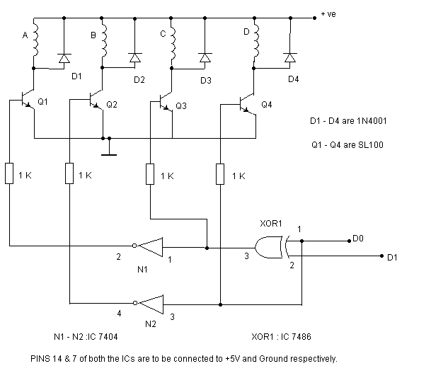
stepper motor controller circuit
The circuit depicted can be utilized to control a unipolar stepper motor equipped with four coils. This design is derived from an older fax machine. The circuit is capable of handling a motor current of approximately 500 mA per winding,...
Pick
The second component is a Signal Distribution Board that transmits voltage, ground, and various signals throughout the system. This board is based on the design found on its dedicated page: Signal Distribution Board. The 7400 pick system is equipped with...
Stepper Motor ControllerCircuit Based On The 7404 IC
The following circuit illustrates a Stepper Motor Controller Circuit Diagram. This circuit is based on the 7404 IC. Features include a simple stepper motor.
The stepper motor controller circuit utilizing the 7404 IC is designed to drive a stepper motor with...
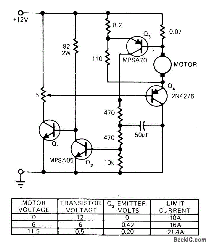
STALLED_MOTOR_PROTECTION
The modification of a basic speed control circuit for small DC permanent-magnet motors implements a maximum current limit during normal operating conditions and a reduced current limit during stall conditions. This design aims to limit the dissipation of series transistor...
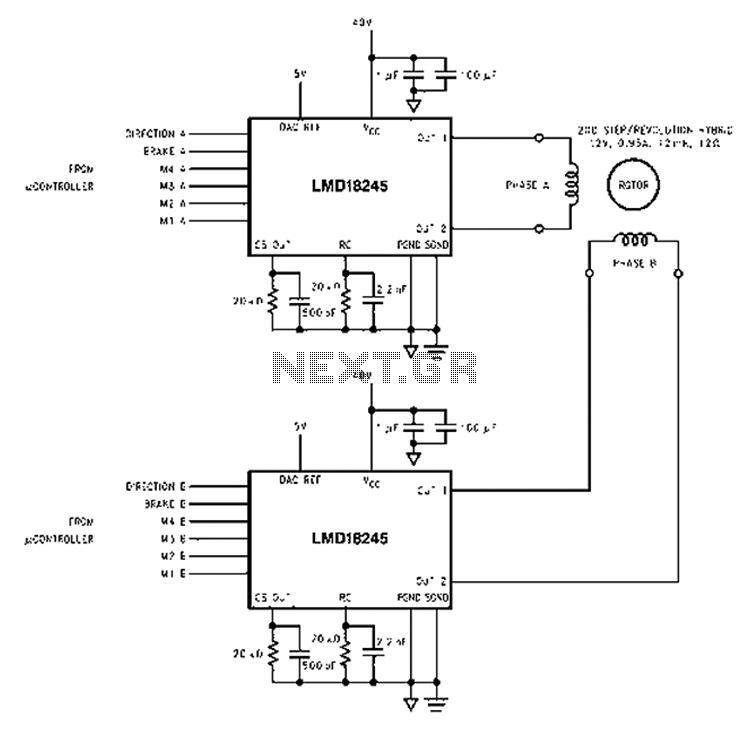
Based LMD18245 bipolar stepper motor control circuit diagram
An innovative current detection method eliminates the power loss associated with the sense resistor in series with the motor. A 4-digit analog converter (DAC) facilitates digital control of the motor current path, simplifying the implementation of full, half, and micro-stepping...
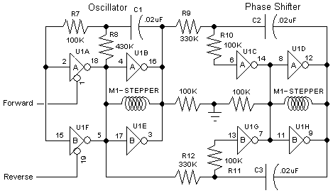
The "BEAM Stepper" drive circuit
The 74AC240 stepper driver works by alternately enabling each half of the buffer. Only one half can be enabled at a time.
Let’s assume that the top half of the driver is enabled. U1A & U1B along with R8, C1,...
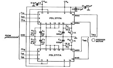
Two Phase Bipolar Stepper Motor Driver Circuit using PBL3717A
The diagram below illustrates a Two Phase Bipolar Stepper Motor Driver utilizing the PBL3717A. It depicts two PBL3717A integrated circuits (ICs) that control and drive two bipolar stepper motors.
The Two Phase Bipolar Stepper Motor Driver circuit is designed to efficiently...
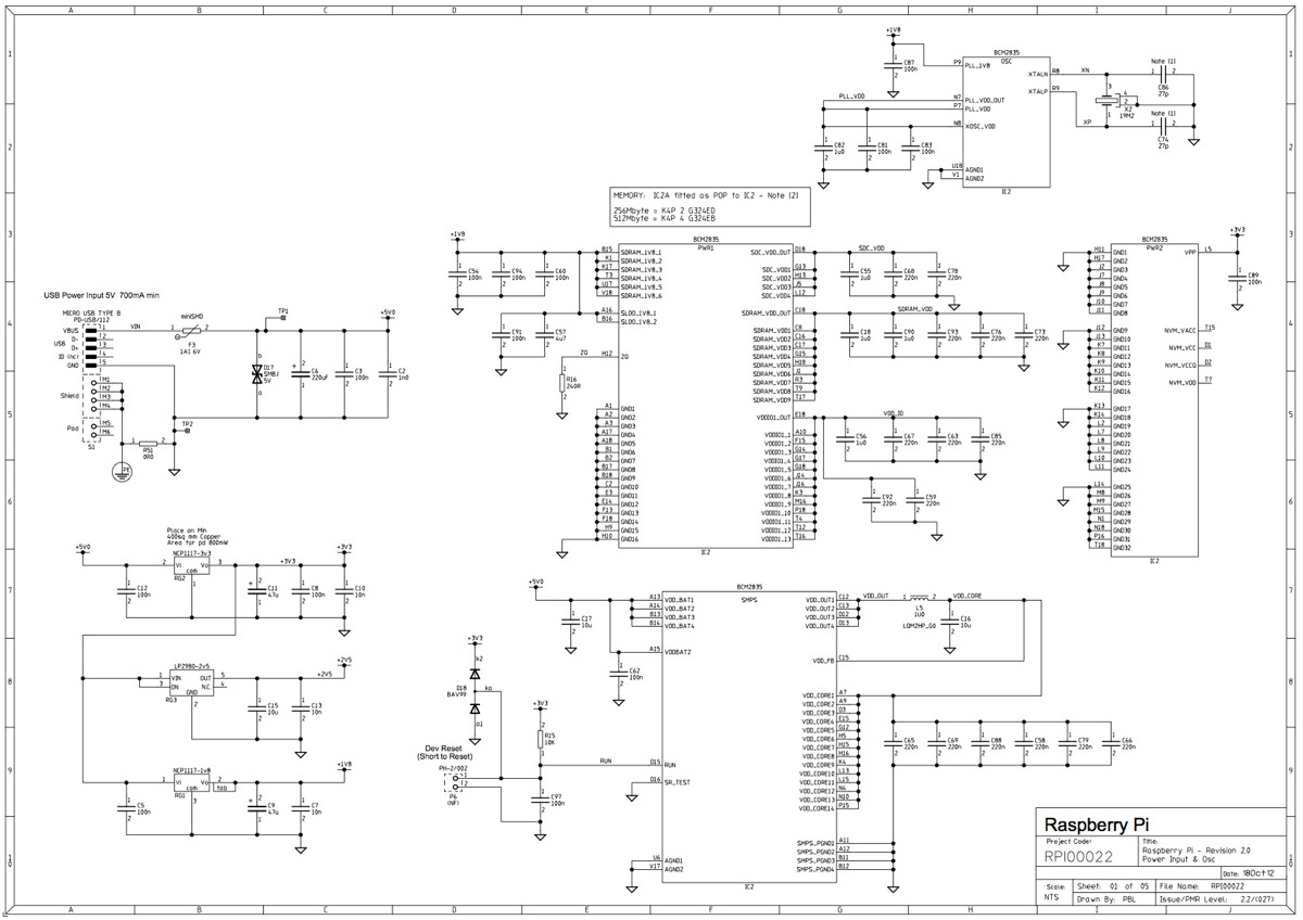
raspberry pi
This post outlines the significant modifications implemented in the latest revision of the board. It is important to note that, while the option to incorporate additional signals into the expansion connector has not yet been utilized, developers of expansion boards...
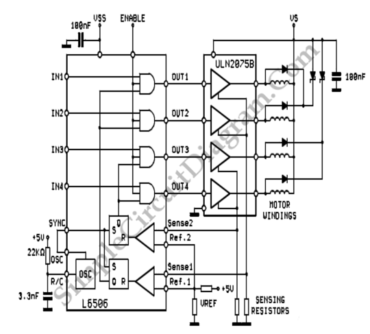
Unipolar 4 Phase Stepper Motor Controller
To sense and control the current in stepping motors and other similar devices, a linear integrated circuit such as the L6506 can be utilized. This chip set enables the formation of a constant current output.
The L6506 is a versatile linear...