


L200 DC Motor Speed Control
#L200
#DC motor
#speed control
#permanent magnet motor
#R1
#R2
#motor driver
#electronics
#circuit design
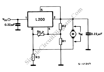
Description: This diagram illustrates the usage of the L200 device for controlling the speed of permanent magnet motors. By utilizing resistors R1 and R2, the desired speed can be achieved.
The L200 is a versatile integrated circuit designed for various applications, including speed control in permanent magnet motors. The circuit typically consists of the L200 chip, which regulates voltage and current to provide efficient motor control.
In this schematic, R1 and R2 are critical components that set the reference voltage and current limits, allowing for precise control over motor speed. The values of these resistors can be calculated based on the desired speed and motor characteristics. A potentiometer can also be employed in place of R2 for adjustable speed settings.
Additional components may include capacitors for filtering and stability, as well as diodes for back EMF protection from the motor. The L200 also requires appropriate power supply connections, typically a DC voltage source, to operate effectively.
The output of the L200 is connected to the motor, where it modulates the voltage supplied to the motor windings. By adjusting the resistance values, the user can finely tune the motor's speed to meet specific application requirements, ensuring optimal performance and efficiency.
Overall, the L200 provides a robust solution for speed control in permanent magnet motors, offering flexibility and precision in various electronic applications.This diagram tells us about how to use L200 device for the speed control of permanent magnet motors. By means of R1 and R2, we can obtain the desired speed,..
The L200 is a versatile integrated circuit designed for various applications, including speed control in permanent magnet motors. The circuit typically consists of the L200 chip, which regulates voltage and current to provide efficient motor control.
In this schematic, R1 and R2 are critical components that set the reference voltage and current limits, allowing for precise control over motor speed. The values of these resistors can be calculated based on the desired speed and motor characteristics. A potentiometer can also be employed in place of R2 for adjustable speed settings.
Additional components may include capacitors for filtering and stability, as well as diodes for back EMF protection from the motor. The L200 also requires appropriate power supply connections, typically a DC voltage source, to operate effectively.
The output of the L200 is connected to the motor, where it modulates the voltage supplied to the motor windings. By adjusting the resistance values, the user can finely tune the motor's speed to meet specific application requirements, ensuring optimal performance and efficiency.
Overall, the L200 provides a robust solution for speed control in permanent magnet motors, offering flexibility and precision in various electronic applications.This diagram tells us about how to use L200 device for the speed control of permanent magnet motors. By means of R1 and R2, we can obtain the desired speed,..
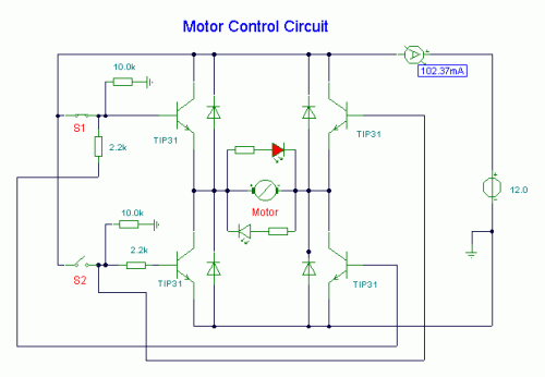
DC Motor Control Circuit
S1 and S2 are normally open, push-to-close, momentary switches. The diodes, which can be either red or green, serve solely to indicate the direction of operation. The TIP31 transistors may need to be adjusted based on the specifications of the...
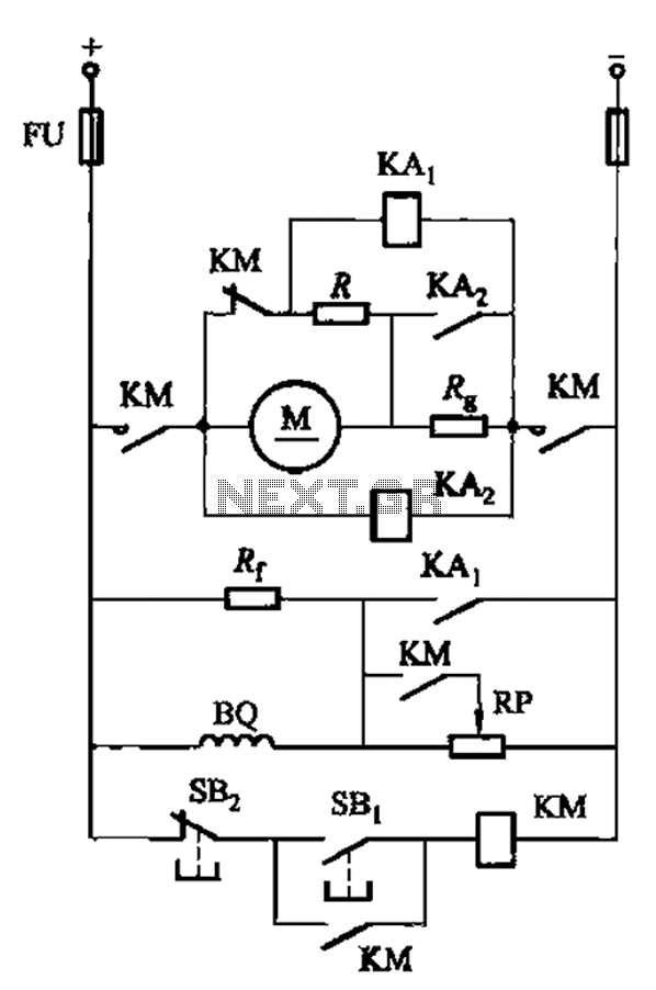
DC motor armature series resistance start dynamic braking circuit of the two-way operation
The circuit illustrated in Figure 3-197 features a dish adjust rheostat (RP) that allows for the adjustment of field current, which in turn modifies the motor speed.
The circuit operates by utilizing a rheostat, which is a variable resistor that can...
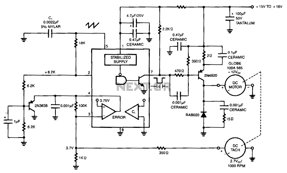
Dc-motor-drive-with-fixed-speed-control
The NE5561 provides pulse-proportional drive and speed control based on DC tachometer feedback. This simple switching circuit consists of a 2N4920 PNP transistor with a commutation diode, which is used to deliver programmed pulse energy to the motor. A frequency...
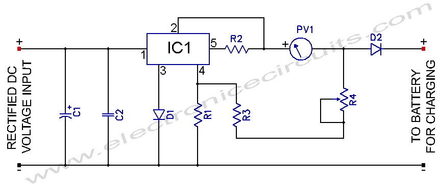
L200 12V Constant Voltage Battery Charger Circuit
L200 12V Constant Voltage Battery Charger Circuit. This battery charger is based on the L200 regulator IC. The L200 is a five-pin adjustable voltage regulator.
The L200 constant voltage battery charger circuit is designed to provide a stable 12V output for...
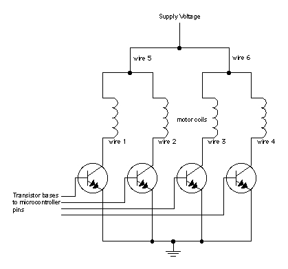
Motor circuits
When moving objects with microcontrollers, three types of motors are particularly useful: DC motors, servomotors, and stepper motors. Most motors operate on the electrical principle of induction. When electric current flows through a wire, it generates a magnetic field around...
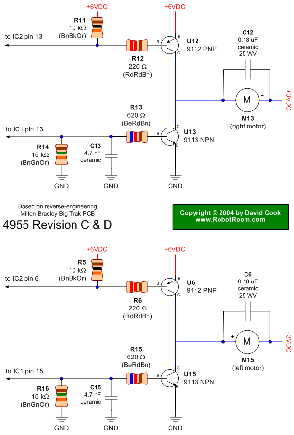
Big Trak Motor Driver Schematic
Schematic of Big Trak's motor driver circuit. The toy includes 9112 and 9113 transistors (and sometimes 2N6715) because the 75494 chip cannot supply enough current to run the Big Trak's motors by itself.
The motor driver circuit for the Big Trak...
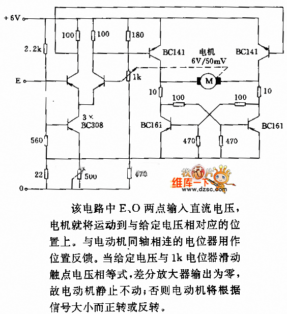
DC motor servo control circuit diagram
In the circuit, when E and O are input DC voltages, the motor moves to a position corresponding to the voltage. A potentiometer, coaxially connected to the motor, is used for position feedback. When the given voltage equals the wiper...
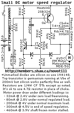
Small DC Motor Speed Regulator
Reverse engineered circuit diagram of a motor speed regulator out of a portable pocket tape recorder containing a single motor for all functions. This circuit works amazingly well, keeping the motor speed constant regardless of shaft load and battery voltage.
The...
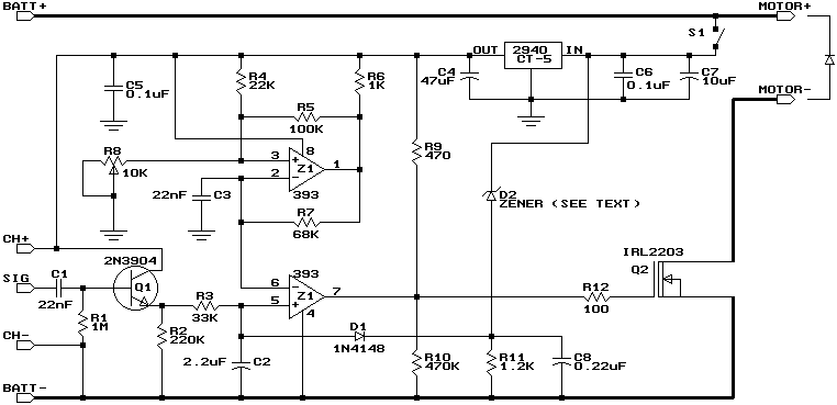
Build a Miniature High-Rate Speed Control with Battery Eliminator Circuit (BEC)
This design is based on a publication by Milan Lulic in the German magazine elektroModell. Lulic's design utilizes surface mount technology (SMT), while this version employs standard off-the-shelf components, making it more accessible for hobbyists. For those interested in a...