


L298N Motor Driver Board Stepper Motor DC Motor Drive
#L298N
#motor driver
#DC motor
#stepper motor
#H-bridge
#PWM control
#dual motor control
#motor drive
#current control
#voltage regulation
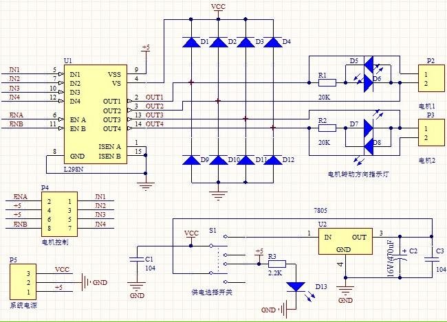
Description:
1. Driver: L298N Dual H Bridge DC Motor Driver IC
2. Supply voltage for the driven part (Vs): +5 V to +35 V; for internal board power supply, Vs: +7 V to +35 V
3. Peak current for the driven part (Io): 2A
4. Supply voltage for the logical part (Vss): +5 V to +7 V (can draw power from the board at +5 V)
5. Operating current range for the logical part: 0 to 36 mA
6. Control signal input voltage range:
Low: -0.3 V ≤ Vin ≤ 1.5 V
High: 2.3 V ≤ Vin ≤ Vss
7. Enable signal input voltage range:
Low: -0.3 V ≤ Vin ≤ 1.5 V (control signal inactive)
High: 2.3 V ≤ Vin ≤ Vss (control signal active)
8. Maximum power consumption: 20 W (at temperature T = 75 °C)
9. Storage temperature: -25 °C to +130 °C
10. Driver board dimensions: 55 mm x 49 mm x 33 mm (including fixed copper pillar and heat sink height)
11. Driver board weight: 33 g
12. Additional features: control of direction indicators, logic part power interface.
The L298N Dual H Bridge DC Motor Driver IC is designed to control the direction and speed of DC motors. It operates with a supply voltage (Vs) ranging from +5 V to +35 V, making it suitable for various applications requiring different power levels. For internal board power, the supply voltage must be maintained between +7 V and +35 V. The driver can handle a peak current of 2A, making it capable of driving larger motors.
The logical section of the driver operates with a supply voltage (Vss) between +5 V and +7 V, allowing it to draw power from the board at +5 V. The operating current for the logical part is specified to be between 0 mA and 36 mA, ensuring efficient control without excessive power consumption.
The control signal input voltage has specific thresholds: a low signal is defined as -0.3 V to 1.5 V, while a high signal is defined as 2.3 V to Vss. This allows for a clear distinction between active and inactive states. The enable signal input follows similar voltage ranges, with low signals indicating an inactive control state and high signals activating the control.
The maximum power consumption of the L298N is rated at 20 W when operating at a temperature of 75 °C, indicating its robustness under load. The component is designed to function in a wide temperature range, from -25 °C to +130 °C, making it suitable for various environmental conditions.
The physical dimensions of the driver board are 55 mm in length, 49 mm in width, and 33 mm in height, including the fixed copper pillar and heat sink, which are essential for thermal management. The total weight of the driver board is 33 g, making it a lightweight option for integration into various systems.
Additionally, the L298N provides features for controlling direction indicators and offers a power interface for the logic part of the board, enhancing its versatility in motor control applications. This driver is ideal for robotics, automation systems, and any application requiring precise motor control.1. Driver: L298N Dual H Bridge DC Motor Driver IC 2. Driven part of the terminal supply area Vs: +5 V ~ +35 V; such as the need to take power within the board, the supply area Vs: +7 V ~ +35 V 3. Driven part of the peak current Io: 2A 4. The logical part of the terminal supply area Vss: +5 V ~ +7 V (can take power within the board +5 V) 5.
The logical part of the operating current range: 0 ~ 36mA 6. Control signal input voltage range: Low:-0.3V ≤ Vin ≤ 1.5V High: 2.3V ≤ Vin ≤ Vss 7. Enable signal input voltage range: Low: -0.3 ≤ Vin ≤ 1.5V (control signal is invalid) High: 2.3V ≤ Vin ≤ Vss (control signal active) 8. Maximum power consumption: 20W (when the temperature T = 75 ) 9. Storage temperature: -25 ~ +130 10. Driver Board Size: 55mm * 49mm * 33mm (with fixed copper pillar and the heat sink height) 11. Driver Board Weight: 33g 12. Other Extensions: control of direction indicators, the logic part of the plate to take power interface.
1. Driver: L298N Dual H Bridge DC Motor Driver IC
2. Supply voltage for the driven part (Vs): +5 V to +35 V; for internal board power supply, Vs: +7 V to +35 V
3. Peak current for the driven part (Io): 2A
4. Supply voltage for the logical part (Vss): +5 V to +7 V (can draw power from the board at +5 V)
5. Operating current range for the logical part: 0 to 36 mA
6. Control signal input voltage range:
Low: -0.3 V ≤ Vin ≤ 1.5 V
High: 2.3 V ≤ Vin ≤ Vss
7. Enable signal input voltage range:
Low: -0.3 V ≤ Vin ≤ 1.5 V (control signal inactive)
High: 2.3 V ≤ Vin ≤ Vss (control signal active)
8. Maximum power consumption: 20 W (at temperature T = 75 °C)
9. Storage temperature: -25 °C to +130 °C
10. Driver board dimensions: 55 mm x 49 mm x 33 mm (including fixed copper pillar and heat sink height)
11. Driver board weight: 33 g
12. Additional features: control of direction indicators, logic part power interface.
The L298N Dual H Bridge DC Motor Driver IC is designed to control the direction and speed of DC motors. It operates with a supply voltage (Vs) ranging from +5 V to +35 V, making it suitable for various applications requiring different power levels. For internal board power, the supply voltage must be maintained between +7 V and +35 V. The driver can handle a peak current of 2A, making it capable of driving larger motors.
The logical section of the driver operates with a supply voltage (Vss) between +5 V and +7 V, allowing it to draw power from the board at +5 V. The operating current for the logical part is specified to be between 0 mA and 36 mA, ensuring efficient control without excessive power consumption.
The control signal input voltage has specific thresholds: a low signal is defined as -0.3 V to 1.5 V, while a high signal is defined as 2.3 V to Vss. This allows for a clear distinction between active and inactive states. The enable signal input follows similar voltage ranges, with low signals indicating an inactive control state and high signals activating the control.
The maximum power consumption of the L298N is rated at 20 W when operating at a temperature of 75 °C, indicating its robustness under load. The component is designed to function in a wide temperature range, from -25 °C to +130 °C, making it suitable for various environmental conditions.
The physical dimensions of the driver board are 55 mm in length, 49 mm in width, and 33 mm in height, including the fixed copper pillar and heat sink, which are essential for thermal management. The total weight of the driver board is 33 g, making it a lightweight option for integration into various systems.
Additionally, the L298N provides features for controlling direction indicators and offers a power interface for the logic part of the board, enhancing its versatility in motor control applications. This driver is ideal for robotics, automation systems, and any application requiring precise motor control.1. Driver: L298N Dual H Bridge DC Motor Driver IC 2. Driven part of the terminal supply area Vs: +5 V ~ +35 V; such as the need to take power within the board, the supply area Vs: +7 V ~ +35 V 3. Driven part of the peak current Io: 2A 4. The logical part of the terminal supply area Vss: +5 V ~ +7 V (can take power within the board +5 V) 5.
The logical part of the operating current range: 0 ~ 36mA 6. Control signal input voltage range: Low:-0.3V ≤ Vin ≤ 1.5V High: 2.3V ≤ Vin ≤ Vss 7. Enable signal input voltage range: Low: -0.3 ≤ Vin ≤ 1.5V (control signal is invalid) High: 2.3V ≤ Vin ≤ Vss (control signal active) 8. Maximum power consumption: 20W (when the temperature T = 75 ) 9. Storage temperature: -25 ~ +130 10. Driver Board Size: 55mm * 49mm * 33mm (with fixed copper pillar and the heat sink height) 11. Driver Board Weight: 33g 12. Other Extensions: control of direction indicators, the logic part of the plate to take power interface.
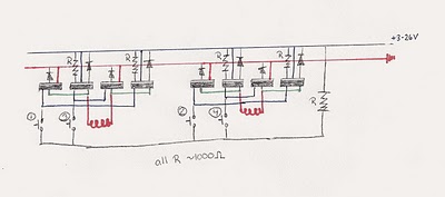
Bipolar Stepper Motor circuit
There was difficulty in understanding that the Source pin connects to low voltage (source of electrons) and the Drain pin connects to high voltage (absorbs electrons). This concept is fundamental to basic electricity, but it required some time to comprehend.
In...
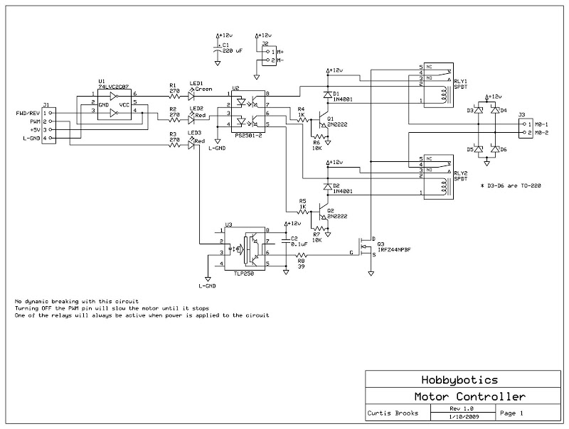
H-bridge circuit
Develop a cost-effective high-current circuit that utilizes PWM. The design includes flyback diodes to protect the MOSFET from the back EMF generated by the motor when the power is switched on and off via the PWM signal. This configuration is...
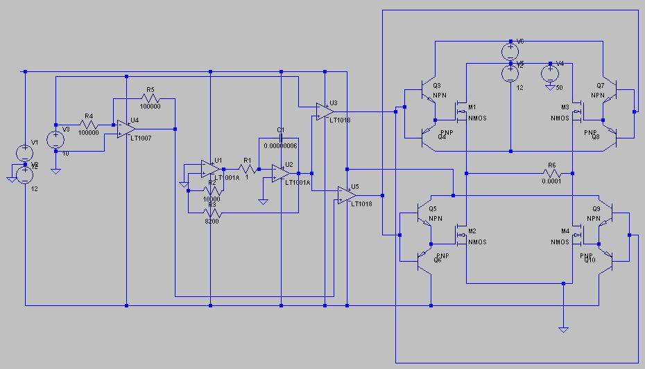
whats wrong my h bridge drivers
I have attempted to create drivers for my H-bridge circuit using complementary emitters; however, the square wave outputs consistently run at a constant 25V instead of a ±10V square wave. The image is somewhat difficult to interpret, but it appears...
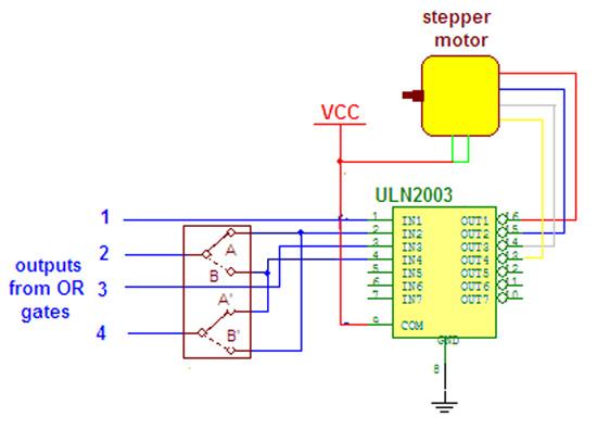
Wireless Stepper Motor Control using Laser and IC555
Wireless stepper motor speed control project using a laser and IC555. This project provides insights into the fundamentals and circuit construction for controlling the speed of a wireless stepper motor utilizing a laser and the IC 555 timer.
The project centers...
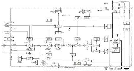
The 4Q2 DC Motor Speed Controller Circuit and Datasheet
This figure represents the 4Q2 DC Motor Speed Controller Circuit Block Diagram, designed for comprehensive control of conventional shunt-wound and permanent magnet motors with a capacity of up to 75 kW, as specified in the datasheet. This type of DC...
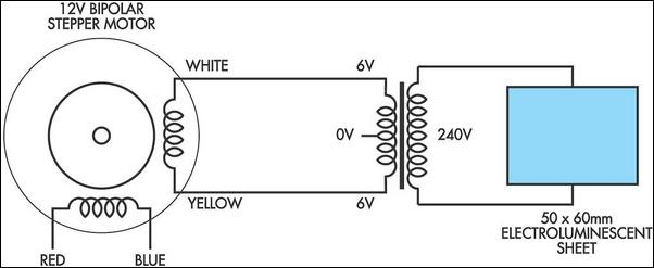
Luminescent Generator
When spun quickly between the fingers, a bipolar stepper motor generates approximately 10VAC. By utilizing a small transformer rated for 240V to 6-0-6V in reverse (with series-connected secondaries), a small bipolar stepper motor can effectively power a standard luminescent sheet...
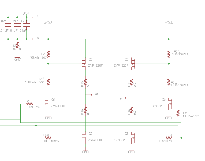
Driving a Capacitive Load with an H-bridge
Following the publication of a previous post, some unusual issues were encountered, which required several days to clarify. The main focus was on building a simple Class D amplifier designed to provide an EL panel with a +/- 120V square...
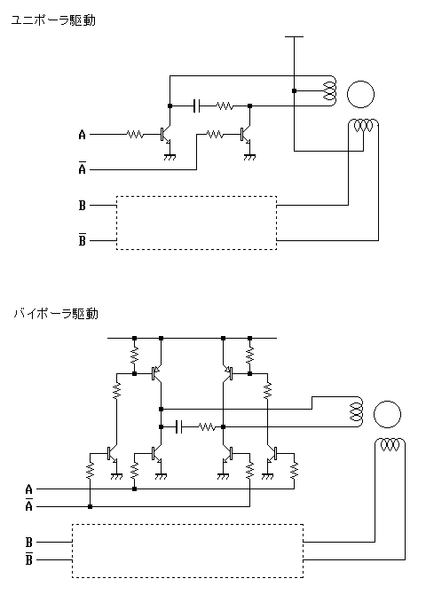
Controlling stepper motors
The first pulse motor that is used to position control. Features were incorporated for positioning control. This does not mean intelligent and autonomous driving the motor in response to movement commands from the host. The key to controlling the pulse...
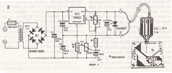
DC Drill Speed Controller Circuit
This DC drill speed controller circuit allows for the adjustment of the rotational speed of a drilling machine. A mini-drill machine is always...
This circuit utilizes a pulse-width modulation (PWM) technique to control the speed of a DC motor, which is...