


LA5522 Application Circuit
#LA5522
#motor control
#supply voltage
#load change
#voltage regulation
#mechanical load
#electronic circuit
#application circuit
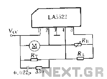
Description: LA5522 Application Circuit. It operates as follows: When the supply voltage (Vcc) changes due to mechanical loads or negative changes, the motor speed may vary. The speed is proportional to the anti-electric potential (E), which also causes changes in the voltage across the motor. An adjustable resistor (R1, R4) samples the voltage (V) reflecting these changes and delivers it to the inverting input terminal of the error amplifier. This voltage is compared with the reference voltage (VREF) at the inverting input. The error amplifier adjusts the output voltage at pin 3 by controlling the base of two transistors. The output voltage at pin 3 and the feedback control exhibit a negative relationship, resulting in closed-loop control that maintains a constant speed.
The LA5522 application circuit is designed for motor speed control, utilizing a feedback mechanism to stabilize the motor's operation under varying load conditions. The circuit is configured to monitor the supply voltage (Vcc), which is critical for the motor's performance. When external factors cause a fluctuation in Vcc, the circuit compensates by adjusting the motor speed accordingly.
The adjustable resistors (R1 and R4) serve as voltage dividers that sample the operational voltage across the motor. This sampled voltage is crucial as it reflects the actual performance of the motor in real-time. The error amplifier plays a pivotal role in this circuit by comparing the sampled voltage with a predetermined reference voltage (VREF). This comparison allows the error amplifier to identify any discrepancies between the desired motor speed and the actual speed.
The output of the error amplifier is linked to the bases of two transistors, which act as a control mechanism for adjusting the motor's power supply. By modulating the base current of these transistors, the output voltage at pin 3 is finely tuned to ensure that the motor operates at the desired speed.
The feedback control system is designed to maintain a negative relationship between the output voltage and the feedback signal. This characteristic is essential for achieving a closed-loop control system that can adapt to changes in load or supply voltage, thereby ensuring that the motor speed remains constant despite external variations.
In summary, the LA5522 application circuit effectively combines voltage sampling, error amplification, and transistor control to provide a reliable motor speed regulation system. This design is particularly useful in applications where precise speed control is necessary, ensuring optimal performance and efficiency of the motor under varying operational conditions.LA5522 Application Circuit It works briefly as follows: When the supply voltage vcc motor mechanical or negative change when the load changes, can cause changes in motor speed. And speed proportional to the anti-electric potential E. Marrow also change accordingly the voltage across the motor also changes. From adjustable resistor 1, 4 on two sampled voltage v ,. Reflects these voltage changes, delivered to the error amplifier inverting input terminal, compare it with the inverting input of the reference voltage VREF, the error amplifier controls the two rear base of the transistor, the output voltage (pin 3) is adjusted. 3-pin output voltage and V. . There was a negative relationship between the feedback control, the results tend to be closed-loop control to maintain a constant speed.
The LA5522 application circuit is designed for motor speed control, utilizing a feedback mechanism to stabilize the motor's operation under varying load conditions. The circuit is configured to monitor the supply voltage (Vcc), which is critical for the motor's performance. When external factors cause a fluctuation in Vcc, the circuit compensates by adjusting the motor speed accordingly.
The adjustable resistors (R1 and R4) serve as voltage dividers that sample the operational voltage across the motor. This sampled voltage is crucial as it reflects the actual performance of the motor in real-time. The error amplifier plays a pivotal role in this circuit by comparing the sampled voltage with a predetermined reference voltage (VREF). This comparison allows the error amplifier to identify any discrepancies between the desired motor speed and the actual speed.
The output of the error amplifier is linked to the bases of two transistors, which act as a control mechanism for adjusting the motor's power supply. By modulating the base current of these transistors, the output voltage at pin 3 is finely tuned to ensure that the motor operates at the desired speed.
The feedback control system is designed to maintain a negative relationship between the output voltage and the feedback signal. This characteristic is essential for achieving a closed-loop control system that can adapt to changes in load or supply voltage, thereby ensuring that the motor speed remains constant despite external variations.
In summary, the LA5522 application circuit effectively combines voltage sampling, error amplification, and transistor control to provide a reliable motor speed regulation system. This design is particularly useful in applications where precise speed control is necessary, ensuring optimal performance and efficiency of the motor under varying operational conditions.LA5522 Application Circuit It works briefly as follows: When the supply voltage vcc motor mechanical or negative change when the load changes, can cause changes in motor speed. And speed proportional to the anti-electric potential E. Marrow also change accordingly the voltage across the motor also changes. From adjustable resistor 1, 4 on two sampled voltage v ,. Reflects these voltage changes, delivered to the error amplifier inverting input terminal, compare it with the inverting input of the reference voltage VREF, the error amplifier controls the two rear base of the transistor, the output voltage (pin 3) is adjusted. 3-pin output voltage and V. . There was a negative relationship between the feedback control, the results tend to be closed-loop control to maintain a constant speed.
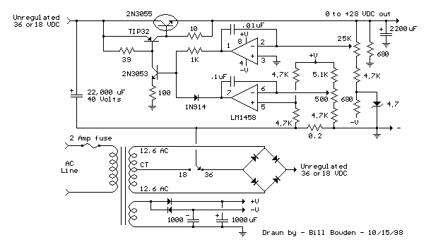
Current and Variable Voltage Power Supply
Another adjustment of application operational amplifiers to adapt a power supply is apparent below. The power supply requires an additional adjustment to supply the op-amps with a bipolar voltage (+/- 8 volts), and the negative voltage is also used to...
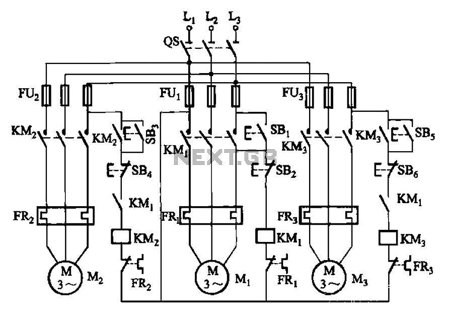
Three motor control circuit start and stop sequence requirements
The circuit shown in Figure 3-89 illustrates a system where starting motor M1 allows motors M2 and M3 to initiate operation. Upon shutdown, motor Mz can be stopped first; however, once motor M1 is stopped (by pressing switch SB2), motors...
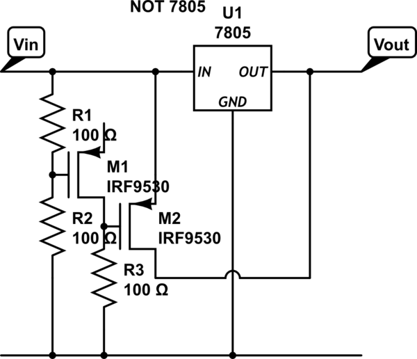
power Voltage supply clipping to <=3.3V
Supply it with a Li-Ion cell, which has a voltage range of 2.7 to 4.2V. The complexity of a buck/boost converter is not desired. While it is possible to regulate the voltage down to anything below 2.5V, it would be...
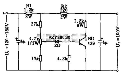
100v / 10ma regulator circuit
The circuit features no-load and short circuit protection mechanisms. To accommodate short circuit conditions, it is necessary to increase resistors R1 and R2 to allow for power dissipation; for example, R1 can be set to 1.2kΩ with a power rating...
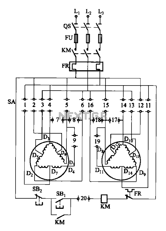
2Y-Y-2 - connection four-speed motor switch control circuit
The 3-119 circuit shown in the figure combines switch SA to realize the stator windings, specifically the 2, Y, and 2Y connections, which correspond to the motor speed n1.
The 3-119 circuit is designed to facilitate the control of motor speed...
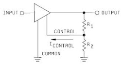
Voltage Regulator
Neither term describes a regulator, only its placement within a circuit or system. Any voltage regulator could meet the requirements, depending on its placement. A listing of Analog Voltage Regulator IC manufacturers. The types of products or devices they produce...
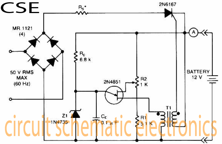
Variable charger circuit Schematic Diagram
The accumulator charger circuit must provide a voltage that matches the specifications of the batteries being charged. For a 12-volt accumulator, the output voltage should not exceed 12 volts, nor should it fall significantly below this threshold. Failure to maintain...
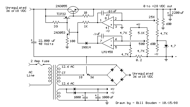
Variable Voltage and Current Power Supply circuit
An alternative approach to utilizing operational amplifiers (op-amps) for power supply regulation is presented. This method necessitates an additional winding on the power transformer to provide the op-amps with a bipolar voltage of +/- 8 volts. The negative voltage generated...
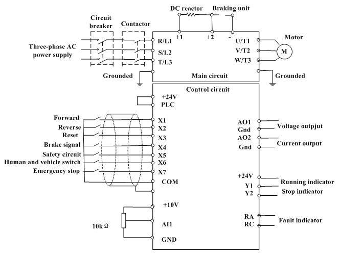
motor control inverter (AC drive) in mine industry
Motor control, energy efficiency of inverter (AC drive) selection, and parameters setting guidance in the mining industry: vector control, open loop or closed loop control, with energy braking unit or energy feedback unit.
In the context of motor control for the...