


LB1948M motor control driver electronic circuit design
#LB1948M
#motor driver
#forward reverse control
#DC motor
#12V system
#low saturation voltage
#2-channel
#parallel connection
#2-phase bipolar
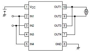
Description: A simple forward-reverse motor control driver electronic circuit can be designed using the LB1948M, a two-channel low saturation voltage forward-reverse motor control driver IC. The LB1948M motor driver is suitable for use in 12V system products and can drive either two DC motors, one DC motor using a parallel connection, or a 2-phase bipolar stepping motor with 1-2 phase excitation mode drive. Some features of the LB1948M motor driver IC include a 12V power supply, low saturation voltage of VO(sat) = 0.5V (typical) at IO = 400mA, zero current draw in standby mode, a braking function, and a built-in thermal shutdown circuit.
The LB1948M motor driver IC is designed for efficient control of DC motors and stepping motors in various applications. It operates within a 12V power supply range, making it suitable for battery-operated devices and low-voltage systems. The low saturation voltage of 0.5V at a current output of 400mA ensures minimal power loss during operation, which is critical for enhancing the overall efficiency of the motor control system.
This motor driver supports multiple configurations, allowing for versatile applications. It can independently drive two DC motors, making it ideal for projects requiring simultaneous control of multiple motors. Alternatively, a single DC motor can be driven using a parallel connection, which can be beneficial in applications that require higher torque or where motor load sharing is necessary. Additionally, the IC is capable of driving a 2-phase bipolar stepping motor, providing flexibility for applications that require precise position control and variable speed operation.
The LB1948M features a zero-current draw in standby mode, which contributes to energy efficiency when the system is not actively driving motors. This feature is particularly advantageous in battery-powered applications, as it extends battery life by minimizing power consumption during idle periods. The braking function integrated into the driver allows for rapid deceleration of the motors, enhancing control and safety in applications where quick stops are required.
Moreover, the built-in thermal shutdown circuit protects the IC from overheating, ensuring reliable operation under varying load conditions. This feature is essential for maintaining the longevity and performance of the motor driver, especially in high-demand scenarios where motors may draw significant current.
Overall, the LB1948M motor driver IC is a robust solution for forward-reverse motor control in various electronic projects, providing essential features and reliable performance for both hobbyist and professional applications.A very simple forward reverse motor control driver electronic circuit project can be designed using the LB1948M 2 channel low saturation voltage forward reverse motor control driver IC. LB1948M motor driver is optimal for motor drive in 12V system products and can drive either two DC motors, one DC motor using parallel connection, or a 2-phase bip
olar stepping motor with 1-2 phase excitation mode drive. Some features of the LB1948M motor driver IC are : 12V power supply, low saturation voltage: VO(sat) = 0. 5V (typical) at IO = 400mA, zero current drawn in standby mode, braking function, built-in thermal shutdown circuit.
The LB1948M motor driver IC is designed for efficient control of DC motors and stepping motors in various applications. It operates within a 12V power supply range, making it suitable for battery-operated devices and low-voltage systems. The low saturation voltage of 0.5V at a current output of 400mA ensures minimal power loss during operation, which is critical for enhancing the overall efficiency of the motor control system.
This motor driver supports multiple configurations, allowing for versatile applications. It can independently drive two DC motors, making it ideal for projects requiring simultaneous control of multiple motors. Alternatively, a single DC motor can be driven using a parallel connection, which can be beneficial in applications that require higher torque or where motor load sharing is necessary. Additionally, the IC is capable of driving a 2-phase bipolar stepping motor, providing flexibility for applications that require precise position control and variable speed operation.
The LB1948M features a zero-current draw in standby mode, which contributes to energy efficiency when the system is not actively driving motors. This feature is particularly advantageous in battery-powered applications, as it extends battery life by minimizing power consumption during idle periods. The braking function integrated into the driver allows for rapid deceleration of the motors, enhancing control and safety in applications where quick stops are required.
Moreover, the built-in thermal shutdown circuit protects the IC from overheating, ensuring reliable operation under varying load conditions. This feature is essential for maintaining the longevity and performance of the motor driver, especially in high-demand scenarios where motors may draw significant current.
Overall, the LB1948M motor driver IC is a robust solution for forward-reverse motor control in various electronic projects, providing essential features and reliable performance for both hobbyist and professional applications.A very simple forward reverse motor control driver electronic circuit project can be designed using the LB1948M 2 channel low saturation voltage forward reverse motor control driver IC. LB1948M motor driver is optimal for motor drive in 12V system products and can drive either two DC motors, one DC motor using parallel connection, or a 2-phase bip
olar stepping motor with 1-2 phase excitation mode drive. Some features of the LB1948M motor driver IC are : 12V power supply, low saturation voltage: VO(sat) = 0. 5V (typical) at IO = 400mA, zero current drawn in standby mode, braking function, built-in thermal shutdown circuit.
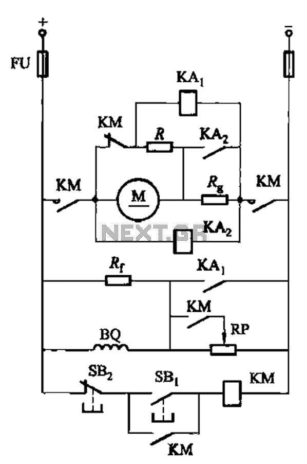
DC motor armature series resistance start dynamic braking circuit of the two-way operation
The circuit illustrated in Figure 3-197 features a dish adjust rheostat (RP) that allows for the adjustment of field current, which in turn modifies the motor speed.
The circuit operates by utilizing a rheostat, which is a variable resistor that can...
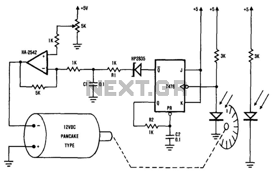
Dc Motor-Speed Control
The system comprises the HA-2542 operational amplifier, a compact 12 V DC motor, and a position encoder. During operation, the encoder generates a series of constant-width pulses that charge capacitor C1. These integrated pulses create a reference voltage proportional to...
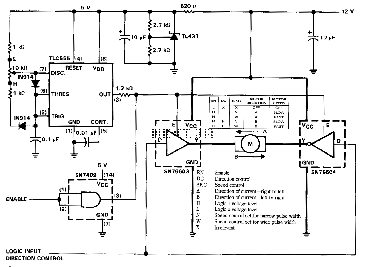
Speed-controlled-reversible-dc-motor-drive
The figure illustrates a reversible DC motor drive application with adjustable speed control. The D inputs for these drivers are complementary and can be tied together and driven from the same logic control for bidirectional motor drive. The enables are...
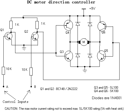
Motor direction controller
This circuit can control a small DC motor, like the one in a tape recorder. When both the points A & B are "HIGH" Q1 and Q2 are in saturation. Hence the bases of Q3 to Q6 are grounded. Hence...
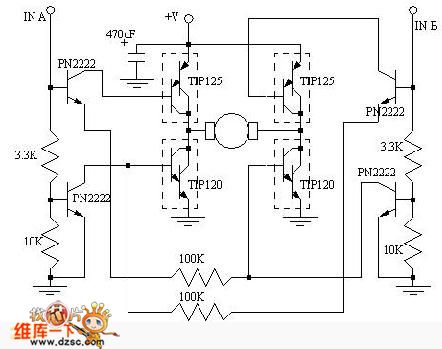
DC Motor Control
Regarding the DC motor control problem, this circuit is intended to assist individuals with specific requirements. The circuit's functions for co-rotation, rollback, deceleration, and stopping can be managed by the connected microcontroller unit (MCU).
The DC motor control circuit is designed...
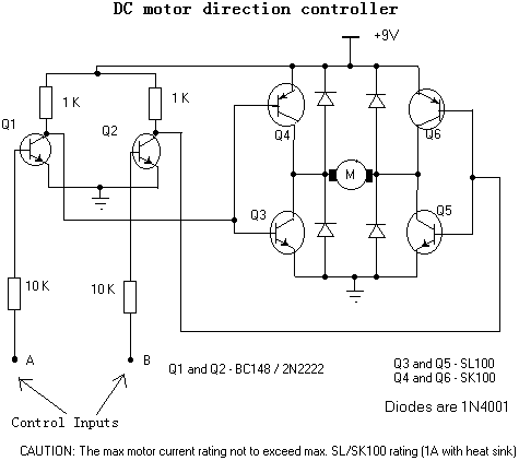
DC Motor Direction Controller
For controlling a small DC motor, such as the one found in a tape recorder, Q1 and Q2 are in saturation when both points A and B are HIGH. Component: ..
To control a small DC motor effectively, a circuit utilizing...
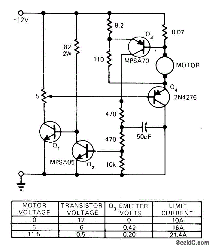
STALLED_MOTOR_PROTECTION
The modification of a basic speed control circuit for small DC permanent-magnet motors implements a maximum current limit during normal operating conditions and a reduced current limit during stall conditions. This design aims to limit the dissipation of series transistor...
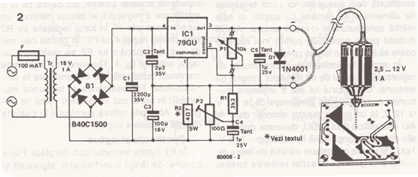
DC Drill Speed Controller Circuit
This DC drill speed controller circuit allows for the adjustment of the rotational speed of a drilling machine. A mini-drill machine is always...
This circuit utilizes a pulse-width modulation (PWM) technique to control the speed of a DC motor, which is...
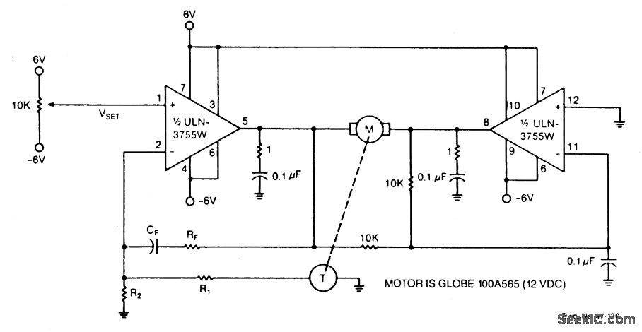
DC MOTOR SPEED CONTROL
Power operational amplifiers provide precise speed control for DC motors. The circuit enables bidirectional speed control. The amplifiers' push-pull configuration guarantees a full rail-to-rail voltage swing (excluding the saturation drops of the output stages) across the motor in both directions....