


Lift control circuit attached to the wall
#elevator
#wound wire induction motor
#vertical transportation
#construction
#drive motor
#high-rise building
#wall-mounted
#industrial
#machinery
#control circuit
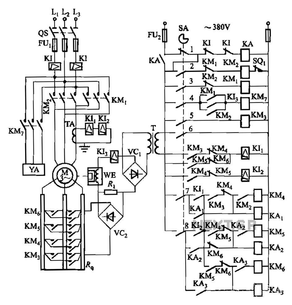
Description: Attached to the wall is a high-rise building construction elevator, an essential piece of vertical transportation machinery. Its drive motor is typically a wound wire induction motor. The main switch and eddy current brake controls are also mounted on the wall of the elevator, as illustrated in the accompanying circuit diagram. The master control contact closure device SA is located in the table.
The described elevator system utilizes a wound wire induction motor, which is commonly employed in vertical transportation applications due to its robustness and efficiency. The motor's operation is controlled by a main switch that regulates power supply, ensuring safe and reliable performance during the elevator's operation.
The eddy current brake system serves as a crucial safety feature, providing controlled deceleration and stopping capabilities. This braking mechanism operates by generating eddy currents in a conductive rotor, creating a magnetic field that opposes the motor's motion. The integration of this braking system enhances the overall safety and operational efficiency of the elevator.
In the circuit diagram, the master control contact closure device (SA) plays a vital role in the control logic of the elevator system. This device is responsible for enabling and disabling the motor’s operation based on the elevator's status and user commands. The configuration of the circuit ensures that the motor and braking systems function in harmony, providing smooth and safe vertical transportation within the high-rise building.
Overall, the combination of the wound wire induction motor, main switch, and eddy current brake, along with the master control contact closure device, forms a comprehensive control system that is essential for the effective operation of construction elevators in high-rise environments. Attached to the wall is a high-rise building construction elevator indispensable vertical transportation machinery. Its drive motor usually wound wire induction motor. Using th e main switch and eddy current brake controls attached to the wall of the elevator typical circuit is shown. FIG master control contact closure device SA in table
The described elevator system utilizes a wound wire induction motor, which is commonly employed in vertical transportation applications due to its robustness and efficiency. The motor's operation is controlled by a main switch that regulates power supply, ensuring safe and reliable performance during the elevator's operation.
The eddy current brake system serves as a crucial safety feature, providing controlled deceleration and stopping capabilities. This braking mechanism operates by generating eddy currents in a conductive rotor, creating a magnetic field that opposes the motor's motion. The integration of this braking system enhances the overall safety and operational efficiency of the elevator.
In the circuit diagram, the master control contact closure device (SA) plays a vital role in the control logic of the elevator system. This device is responsible for enabling and disabling the motor’s operation based on the elevator's status and user commands. The configuration of the circuit ensures that the motor and braking systems function in harmony, providing smooth and safe vertical transportation within the high-rise building.
Overall, the combination of the wound wire induction motor, main switch, and eddy current brake, along with the master control contact closure device, forms a comprehensive control system that is essential for the effective operation of construction elevators in high-rise environments. Attached to the wall is a high-rise building construction elevator indispensable vertical transportation machinery. Its drive motor usually wound wire induction motor. Using th e main switch and eddy current brake controls attached to the wall of the elevator typical circuit is shown. FIG master control contact closure device SA in table
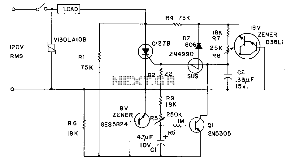
Burst-power-control
Industrial applications sometimes require that power be briefly applied to a load following the closure of a switch, such as a microswitch or foot switch. The load could be a heating element used for sealing plastic bags, a DC motor...
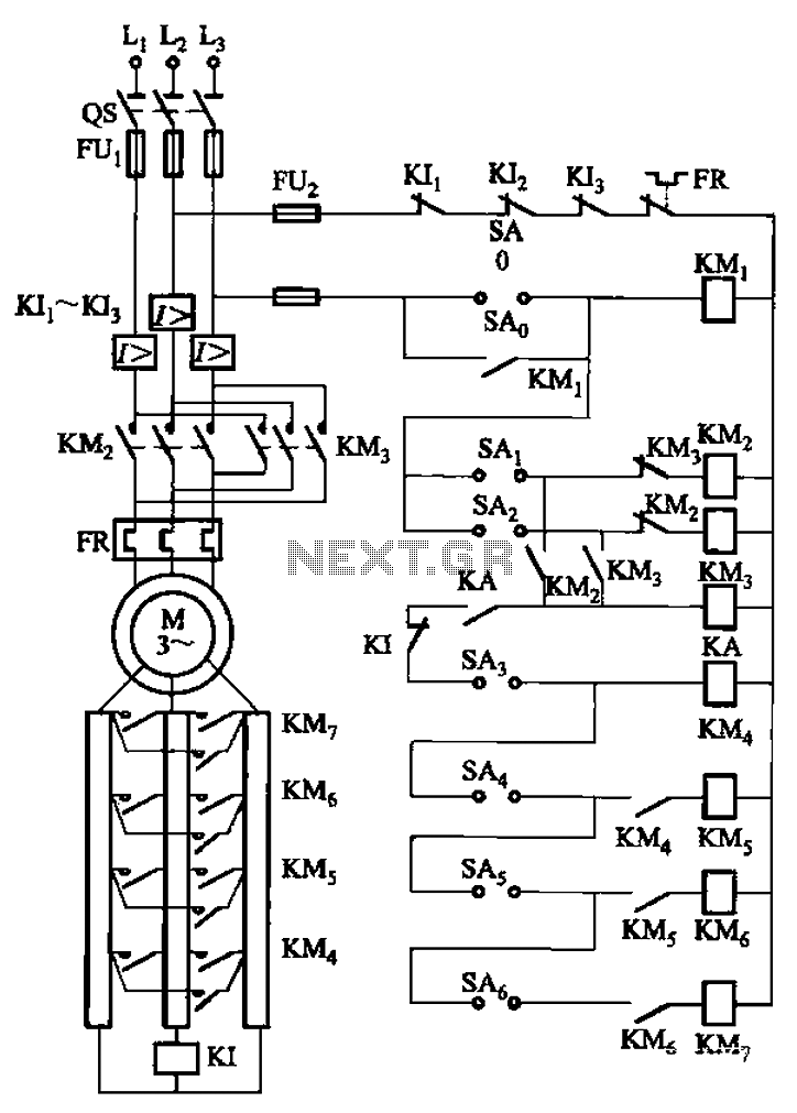
A control circuit reversing braking and reverse grading speed control function
The circuit depicted in Figure 3-168 utilizes a controller for speed grading and reversing control. A reverse brake is connected to the rotor circuit through an overcurrent relay, labeled KI, for control. The current relay KIi to KI3 serves as...
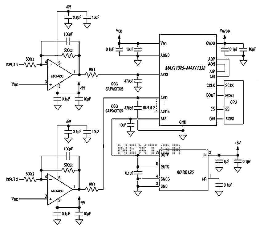
Simple and practical circuit diagram of an elevator failure alarm
In the event of a sudden power failure in an elevator, it is crucial for the duty officer in the distribution room to be alerted promptly to prevent panic among passengers trapped inside. The following describes a sound alarm circuit...