


LMD18200 motor controller electronic project
#LMD18200
#H-Bridge
#DC motor
#stepper motor
#current sensing
#National Semiconductors
#motion control
#3A
#6A peak
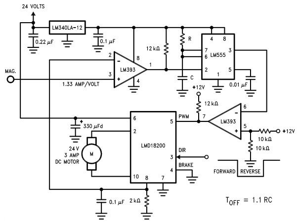
Description: The LMD18200 3A H-Bridge, designed by National Semiconductors, can be used to create a simple motor controller electronic project suitable for motion control applications. This component is ideal for driving both DC and stepper motors, accommodating peak output currents of up to 6A. An innovative circuit has been implemented to facilitate low-loss sensing of the output current. This circuit regulates the motor current by applying an average voltage of zero to the motor terminals for a specified duration whenever the motor current exceeds the commanded level. This results in a slight variation of the motor current around a controlled average level. The duration of the off period is determined by a resistor and capacitor combination associated with the LM555 timer.
The LMD18200 H-Bridge is a versatile motor driver capable of delivering high currents, making it suitable for various motor control applications. The device features integrated protection mechanisms, including thermal shutdown and current limiting, which enhance reliability during operation. The H-Bridge configuration allows for bidirectional control of the motor, enabling both forward and reverse rotation by simply changing the polarity of the input signals.
The low-loss sensing circuit is a critical feature that ensures efficient operation of the motor. By measuring the output current and comparing it to the desired current, the circuit can dynamically adjust the voltage applied to the motor. This feedback mechanism is crucial for maintaining consistent performance, especially under varying load conditions. The LM555 timer plays a key role in this system, generating precise timing intervals that dictate when the motor terminals should be effectively shorted to ground, thus controlling the average current flowing through the motor.
The selection of resistor and capacitor values in the LM555 timing circuit directly influences the response time and stability of the current regulation. A larger capacitor will result in a longer off period, which can be beneficial in smoothing out current spikes but may also lead to slower response times. Conversely, a smaller capacitor will allow for quicker adjustments but may increase the risk of oscillations if not properly tuned.
In summary, the LMD18200 H-Bridge, combined with the LM555 timer for current regulation, forms a robust motor control solution. This design is particularly useful in applications requiring precise control of motor speed and torque, such as in robotics, CNC machines, and automated systems. Proper implementation of this circuit can lead to improved performance and efficiency in various motion control tasks.Using the LMD18200 3A H-Bridge designed by National Semiconductors for motion control applications can be designed a very simple motor controller electronic project. Ideal for driving DC and stepper motors; the LMD18200 accommodates peak output currents up to 6A. An innovative circuit which facilitates low-loss sensing of the output current has b een implemented. This circuit controls the current through the motor by applying an average voltage equal to zero to the motor terminals for a fixed period of time, whenever the current through the motor exceeds the commanded current. This action causes the motor current to vary slightly about an externally controlled average level. The duration of the Off-period is adjusted by the resistor and capacitor combination of the LM555.
The LMD18200 H-Bridge is a versatile motor driver capable of delivering high currents, making it suitable for various motor control applications. The device features integrated protection mechanisms, including thermal shutdown and current limiting, which enhance reliability during operation. The H-Bridge configuration allows for bidirectional control of the motor, enabling both forward and reverse rotation by simply changing the polarity of the input signals.
The low-loss sensing circuit is a critical feature that ensures efficient operation of the motor. By measuring the output current and comparing it to the desired current, the circuit can dynamically adjust the voltage applied to the motor. This feedback mechanism is crucial for maintaining consistent performance, especially under varying load conditions. The LM555 timer plays a key role in this system, generating precise timing intervals that dictate when the motor terminals should be effectively shorted to ground, thus controlling the average current flowing through the motor.
The selection of resistor and capacitor values in the LM555 timing circuit directly influences the response time and stability of the current regulation. A larger capacitor will result in a longer off period, which can be beneficial in smoothing out current spikes but may also lead to slower response times. Conversely, a smaller capacitor will allow for quicker adjustments but may increase the risk of oscillations if not properly tuned.
In summary, the LMD18200 H-Bridge, combined with the LM555 timer for current regulation, forms a robust motor control solution. This design is particularly useful in applications requiring precise control of motor speed and torque, such as in robotics, CNC machines, and automated systems. Proper implementation of this circuit can lead to improved performance and efficiency in various motion control tasks.Using the LMD18200 3A H-Bridge designed by National Semiconductors for motion control applications can be designed a very simple motor controller electronic project. Ideal for driving DC and stepper motors; the LMD18200 accommodates peak output currents up to 6A. An innovative circuit which facilitates low-loss sensing of the output current has b een implemented. This circuit controls the current through the motor by applying an average voltage equal to zero to the motor terminals for a fixed period of time, whenever the current through the motor exceeds the commanded current. This action causes the motor current to vary slightly about an externally controlled average level. The duration of the Off-period is adjusted by the resistor and capacitor combination of the LM555.
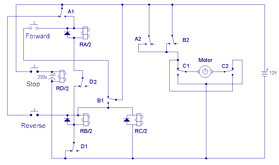
DC Motor Reversing Circuit
A DC motor reversing circuit using non-latching push button switches. Relays control forward, stop, and reverse action, and the motor cannot be switched from forward to reverse unless the stop switch is pressed first.
The described circuit employs a system of...
Design a Unipolar Stepper Motor Controller/Driver and
A motor coil requires controllers to adjust its position and speed. A motor driver is necessary to amplify the low output current from a controller to a larger current required by the motor. The following article describes how to design...

how H-brigde is working
Please help me understand how this H-bridge works. I have tried, but I couldn't make any sense of it. I know the general functioning of the circuit, but I don't fully grasp the details.
An H-bridge is a specific type of...
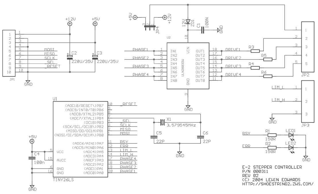
Stepper Motor Controller
Stepper motors are beneficial for low-speed, intermediate-torque drive and positioning applications, especially where precise sub-revolution rotor position control is required. These motors are frequently utilized to drive the reels of electromechanical slot machines, position floppy disk drive heads, operate camera...
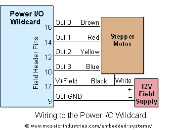
Controlling Stepper Motors Using Power IO Wildcard MOSFET Driver
For optimal efficiency, set MAX_STEPPERS to the number of stepper motors being controlled, with a maximum limit of four. Motors are identified by indices 0, 1, 2, and 3. On the QCard, there is a trade-off between the number of...
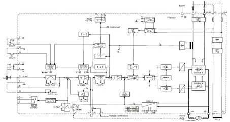
The 4Q2 DC Motor Speed Controller Circuit and Datasheet
This figure represents the 4Q2 DC Motor Speed Controller Circuit Block Diagram, designed for comprehensive control of conventional shunt-wound and permanent magnet motors with a capacity of up to 75 kW, as specified in the datasheet. This type of DC...
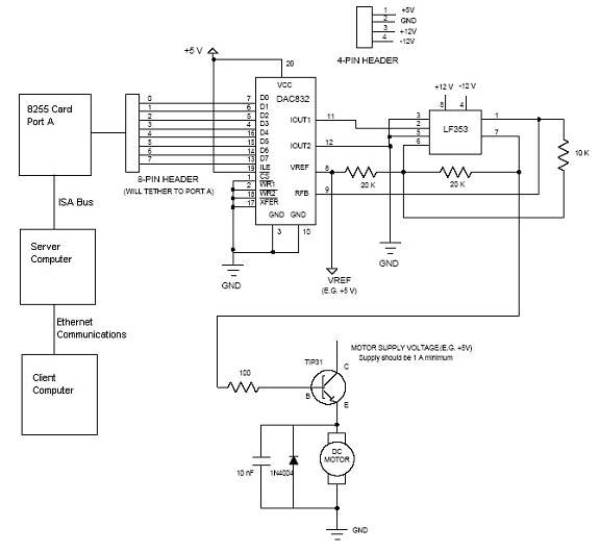
Open Loop Speed Control of a DC Motor via 8255 Controller
Open loop speed control of a DC motor is implemented using the 8255 Digital I/O Controller chip in conjunction with a TCP/IP server-client application programmed in Visual Basic. The DAC0832 chip serves as the Digital to Analog Converter. This project...
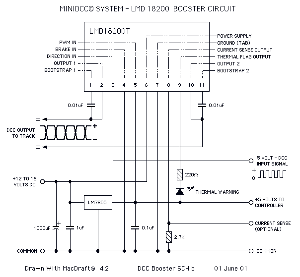
H Bridge Direct Current Motor Control Circuits
This page features H-Bridge circuits used for controlling direct current motors. Several designs are shown using both CMOS and Bi-Polar power devices. These circuits could be used as the basis for Model Railroad DCC Boosters or PWM motor controllers. The...

Precise Camera Panning with Stepper Motors
The prototype circuit board utilized an external LCD display that received commands through an RS-232 interface. While this setup functioned adequately, programming it was cumbersome. Consequently, the circuit board was revised to support a directly attached LCD display. The image...