


Motor electronic speed controller circuit diagram 7
#wireless remote control
#transmitter
#receiver
#speed controller
#IC module
#time-base integrated circuit
#diodes
#motor driver
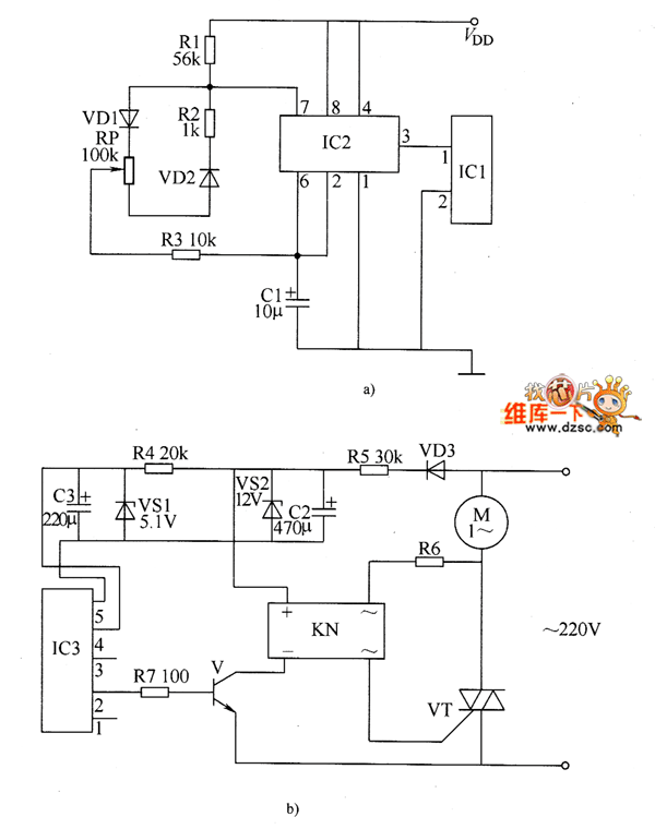
Description: The electronic motor speed controller circuit includes a wireless remote control transmitter circuit and a wireless remote control receiver circuit, as illustrated in the accompanying chart. The wireless remote control transmitter circuit comprises a micro-power wireless remote control transmitter IC module (IC1), a time-base integrated circuit (IC2), and diodes VD1 and VD2.
The electronic motor speed controller circuit is designed to facilitate the remote control of motor speed, enhancing operational flexibility in various applications. The transmitter section utilizes a micro-power wireless remote control transmitter IC module (IC1) that generates control signals. This module is typically designed to operate at low power, ensuring longevity and efficiency in battery-operated devices.
The time-base integrated circuit (IC2) plays a critical role in generating precise timing signals, which are essential for modulating the output frequency sent to the motor. This modulation is vital for achieving varying speed levels in the motor operation. The inclusion of diodes VD1 and VD2 serves to protect the circuit from reverse polarity and voltage spikes, ensuring the integrity and longevity of the components.
The receiver circuit, which is not detailed in the initial description but is implied, would typically include a corresponding wireless receiver module that decodes the signals transmitted by the transmitter. This module would then relay the control signals to a motor driver circuit, which translates the signals into appropriate voltage and current levels to control the motor speed effectively.
Overall, the integration of these components enables a reliable and efficient wireless control system for motor speed regulation, suitable for applications ranging from remote-controlled vehicles to automated industrial processes.The electronic motor speed controller circuit consists of wireless remote control transmitter circuit, wireless remote control receiver control circuit, and it is shown as the chart. Wireless remote control transmitter circuit is composed of the micro-power wireless remote control transmitter IC module IC1, time-base integrated circuit IC2, diodes vD1, VD2,..
The electronic motor speed controller circuit is designed to facilitate the remote control of motor speed, enhancing operational flexibility in various applications. The transmitter section utilizes a micro-power wireless remote control transmitter IC module (IC1) that generates control signals. This module is typically designed to operate at low power, ensuring longevity and efficiency in battery-operated devices.
The time-base integrated circuit (IC2) plays a critical role in generating precise timing signals, which are essential for modulating the output frequency sent to the motor. This modulation is vital for achieving varying speed levels in the motor operation. The inclusion of diodes VD1 and VD2 serves to protect the circuit from reverse polarity and voltage spikes, ensuring the integrity and longevity of the components.
The receiver circuit, which is not detailed in the initial description but is implied, would typically include a corresponding wireless receiver module that decodes the signals transmitted by the transmitter. This module would then relay the control signals to a motor driver circuit, which translates the signals into appropriate voltage and current levels to control the motor speed effectively.
Overall, the integration of these components enables a reliable and efficient wireless control system for motor speed regulation, suitable for applications ranging from remote-controlled vehicles to automated industrial processes.The electronic motor speed controller circuit consists of wireless remote control transmitter circuit, wireless remote control receiver control circuit, and it is shown as the chart. Wireless remote control transmitter circuit is composed of the micro-power wireless remote control transmitter IC module IC1, time-base integrated circuit IC2, diodes vD1, VD2,..
Receiver/Scanner Preamp Circuit
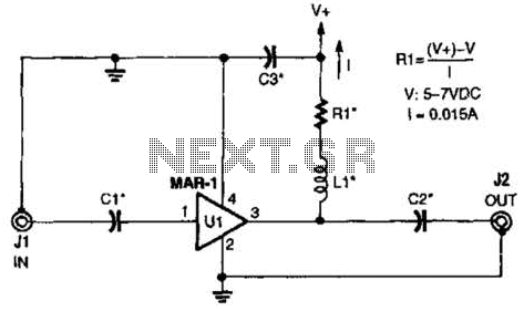
The low-cost Mini-Circuits MAR-X series of chips provides a significant advantage for RF builders, featuring inherent 50-ohm input and output impedances essential for RF systems. An MAR-1-based receiver/scanner preamplifier is illustrated. Capacitors Ci and C2 are chip capacitors, with values...
Onkyo TX2500 mk II
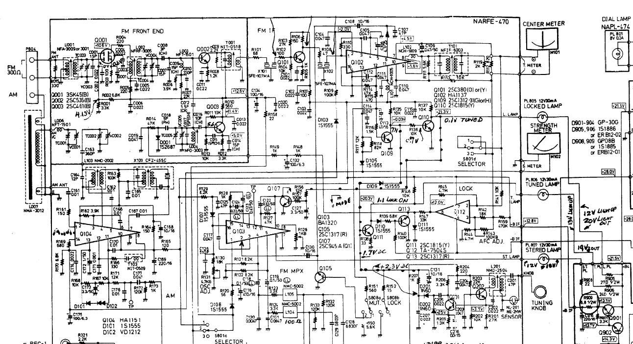
An Onkyo TX2500 mk II receiver is being repaired for a friend, but it is experiencing issues with both AM and FM tuning, resulting in low reception quality.
The Onkyo TX2500 mk II is a vintage audio receiver known for its...
Remote Control Transmitter Circuit
This transmitter can be utilized for multiple applications. An INS8048L microprocessor produces various codes based on keypad inputs. These codes are modulated onto a 40-kHz carrier frequency. Additionally, Q1 drives infrared LEDs LED1 and LED2.
The transmitter circuit primarily consists of...
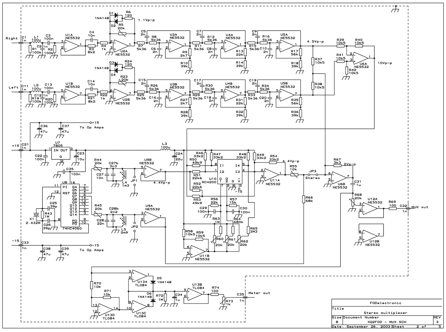
80 Watt stereo transmitter
This transmitter was designed from the ground up to provide very high sound quality, coupled with excellent frequency stability, reliability, etc. It can be used as a standalone transmitter to serve a medium-sized town, or as an exciter to drive...
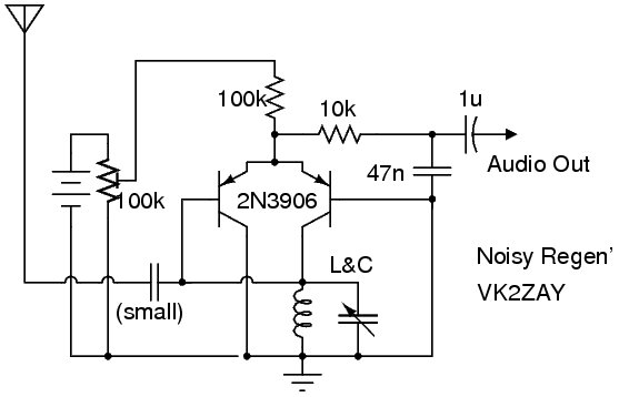
Noisy Regen Receiver
The following circuit illustrates a Noisy Regenerative Receiver Circuit Diagram. Features include a Noisy Regenerative Receiver Circuit, which simplifies the process of...
The Noisy Regenerative Receiver Circuit is designed to amplify weak radio frequency signals while also incorporating a regenerative feedback...
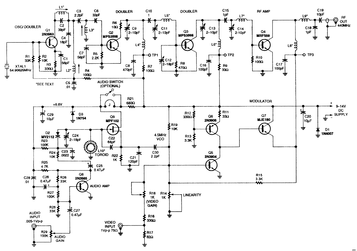
MINI_ATV_TRANSMITTER
This low-power NTSC video and sound transmitter is suitable for amateur radio, video handheld transceivers, remote control applications, and surveillance purposes. It features a crystal oscillator-multiplier and a power amplifier. Video modulation is achieved through a three-transistor series modulator. The...
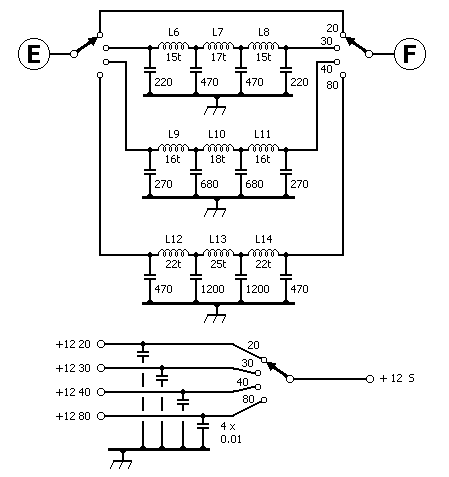
radio mf tx
There has been a longstanding interest in constructing a simple VXO transmitter, though concerns regarding the limited tuning range typically associated with VXOs on busy HF bands have been present. The capability to switch between multiple crystals and cover various...
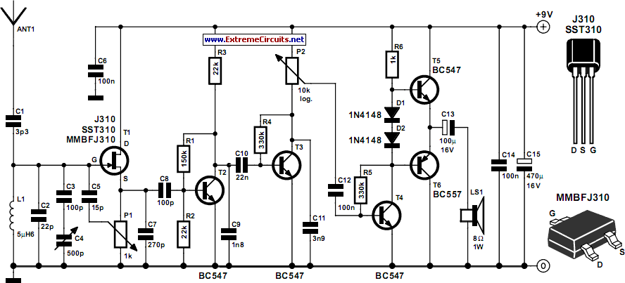
Tuned Radio Frequency (TRF) Receiver
Superheterodyne receivers have been mass-produced since around 1924, but for reasons of cost did not become successful until the 1930s.
Superheterodyne receivers represent a pivotal advancement in radio technology, characterized by their ability to convert high-frequency signals into lower intermediate...
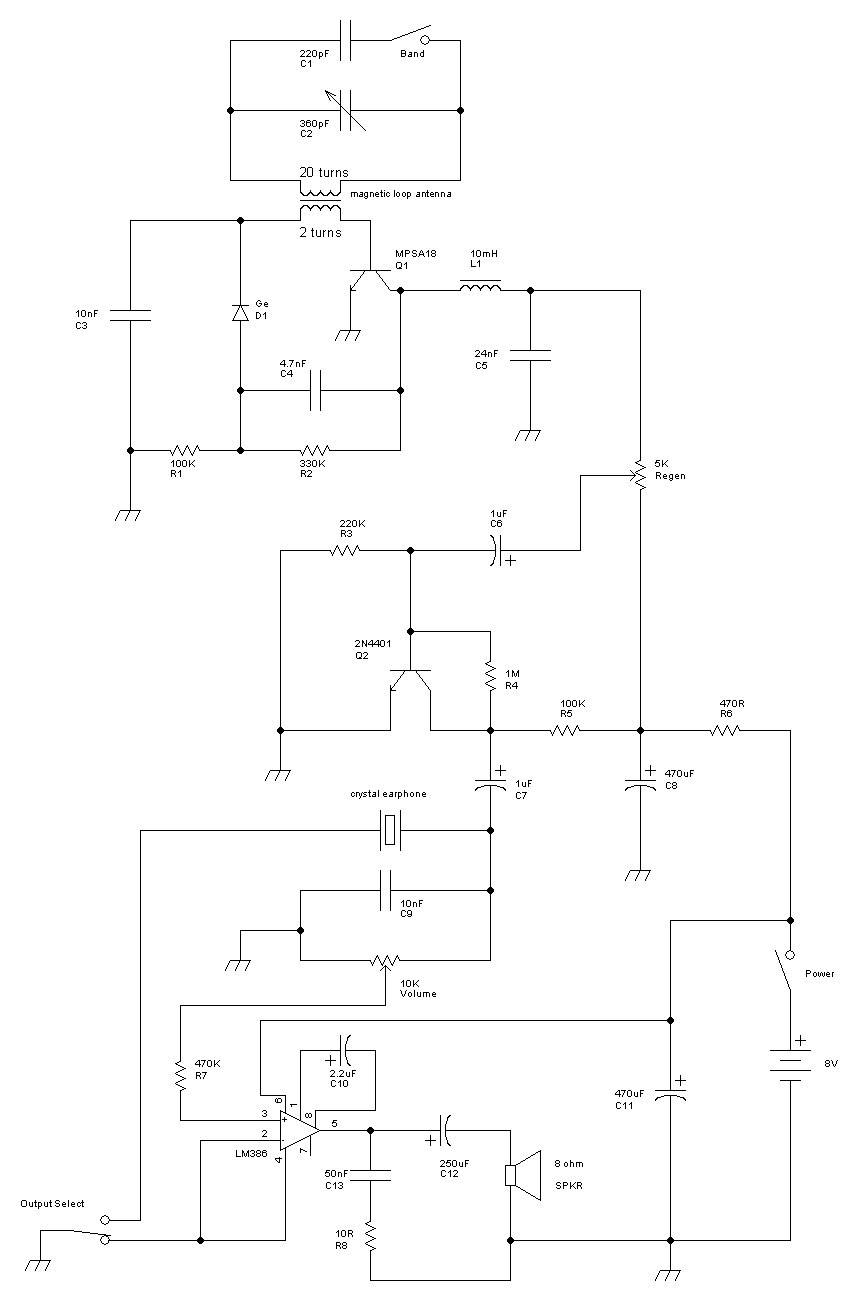
Radio circuits built
This receiver is a modification of Charles Wenzel's Two Transistor Reflex Radio. Instead of a ferrite AM loopstick antenna, a magnetic loop antenna is used, and an LM386 amplifier stage has been added to drive an 8-ohm speaker. A switch...