


Motor Speed and Speed protection circuit of small hydropower stations
#variable speed motor
#hydropower
#governor
#power switch
#speed protection
#motor control
#grid
#electric
#switch
#circuit protection
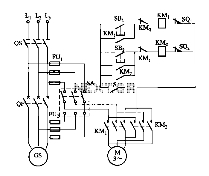
Description: FIG M is a variable speed motor control for the opening and closing of a wicket gate. It features an electric governor. The system is activated by a power switch (SA) located on the front grid, and a toggle switch (S) is opened. After the grid is engaged, the generator side (SA) is activated, and switch S is closed to ensure self-protection. When the generator operates under full load, a limit switch (SQi) at the top opens to stop the motor. Additionally, when the turbine guide vane is fully closed, another limit switch (SQ) opens, stopping the motor. For speed protection, if the generator fails and trips the circuit breaker (QF), its auxiliary contact closes, activating contactor (KMz) to reverse the motor until limit switch (SQz) at the top opens, completing the shutdown process.
The variable speed motor control system for the wicket gate is designed to manage the precise operation of the gate through a combination of switches and limit sensors. The power switch (SA) initiates the control system, allowing for the toggling of switch (S) to enable the motor operation. The integration of an electric governor ensures that the motor's speed is regulated according to the operational requirements of the generator.
The system incorporates several safety features to protect both the motor and the generator. The limit switch (SQi) serves as a critical component, halting the motor when the generator reaches full load conditions, thereby preventing potential overload situations. Similarly, the operation of the turbine guide vane is monitored by limit switch (SQ), which stops the motor when the gate is fully closed, ensuring that the system does not operate outside its designed parameters.
In the event of a generator failure, the circuit breaker (QF) plays a vital role in the protection mechanism. Upon tripping, the auxiliary contact of the circuit breaker closes, which energizes contactor (KMz). This action causes the motor to reverse its direction, allowing the wicket gate to return to a safe position until limit switch (SQz) indicates that the gate is fully open, thus completing the emergency shutdown sequence.
Overall, the design of this motor control system emphasizes reliability and safety, utilizing a combination of mechanical and electrical components to ensure effective operation while minimizing risks associated with generator and motor failures.FIG, M is a variable speed motor control wicket opening and closing and opening. O electric governor. Front grid, hit the power switch SA A side, toggle switch S is opened; aft er the grid, SA play and be in the generator side, S is closed, the trip in order to achieve self-protection purposes. When the generator grid, with full load, limit switch off SQi top open, the motor is stopped; when off, when the turbine guide vane opening is zero, the limit switch so: the top open, the motor is stopped.
Speed protection. When the generator fails, tripping the circuit breaker QF, its auxiliary contact is closed, the contactor KMz was electric pull, reverse the motor until the limit switch sQz top open, shut down is completed.
The variable speed motor control system for the wicket gate is designed to manage the precise operation of the gate through a combination of switches and limit sensors. The power switch (SA) initiates the control system, allowing for the toggling of switch (S) to enable the motor operation. The integration of an electric governor ensures that the motor's speed is regulated according to the operational requirements of the generator.
The system incorporates several safety features to protect both the motor and the generator. The limit switch (SQi) serves as a critical component, halting the motor when the generator reaches full load conditions, thereby preventing potential overload situations. Similarly, the operation of the turbine guide vane is monitored by limit switch (SQ), which stops the motor when the gate is fully closed, ensuring that the system does not operate outside its designed parameters.
In the event of a generator failure, the circuit breaker (QF) plays a vital role in the protection mechanism. Upon tripping, the auxiliary contact of the circuit breaker closes, which energizes contactor (KMz). This action causes the motor to reverse its direction, allowing the wicket gate to return to a safe position until limit switch (SQz) indicates that the gate is fully open, thus completing the emergency shutdown sequence.
Overall, the design of this motor control system emphasizes reliability and safety, utilizing a combination of mechanical and electrical components to ensure effective operation while minimizing risks associated with generator and motor failures.FIG, M is a variable speed motor control wicket opening and closing and opening. O electric governor. Front grid, hit the power switch SA A side, toggle switch S is opened; aft er the grid, SA play and be in the generator side, S is closed, the trip in order to achieve self-protection purposes. When the generator grid, with full load, limit switch off SQi top open, the motor is stopped; when off, when the turbine guide vane opening is zero, the limit switch so: the top open, the motor is stopped.
Speed protection. When the generator fails, tripping the circuit breaker QF, its auxiliary contact is closed, the contactor KMz was electric pull, reverse the motor until the limit switch sQz top open, shut down is completed.
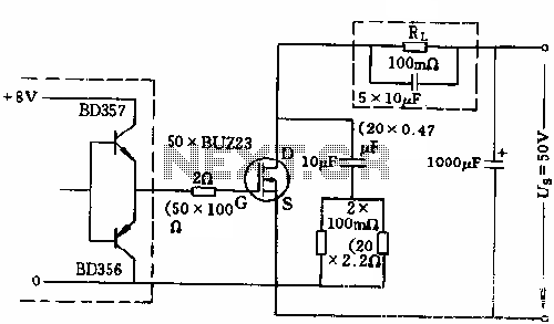
500A power switch control circuit diagram
The circuit employs 50 BUZ23 field effect transistors (FETs) arranged in parallel, with a tube blocking voltage of 100V. The control power required is minimal, eliminating the risks associated with second breakdown and the positive temperature coefficient phenomenon in the...
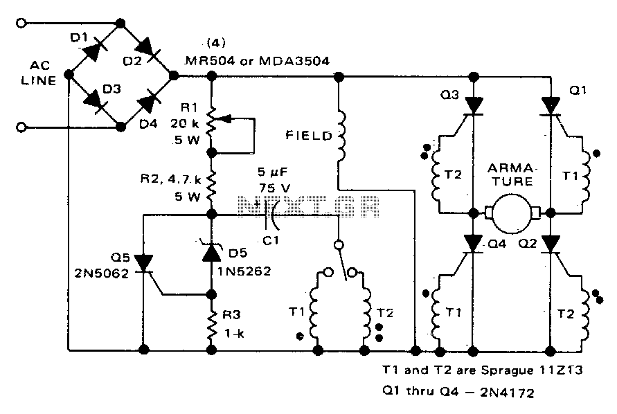
Direction and speed control
This circuit functions similarly to the one depicted in Fig. 57-4. The key differences include the placement of the field across the rectified supply and the armature being positioned within the SCR bridge. Therefore, the field current is unidirectional while...
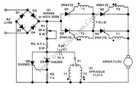
Series-Wound Direction And Speed Motor Control
This is a motor controller circuit that controls the speed and direction of series-wound motors. This circuit employs silicon controlled rectifiers (SCR).
The motor controller circuit is designed to manage both the speed and direction of series-wound motors, which are commonly...
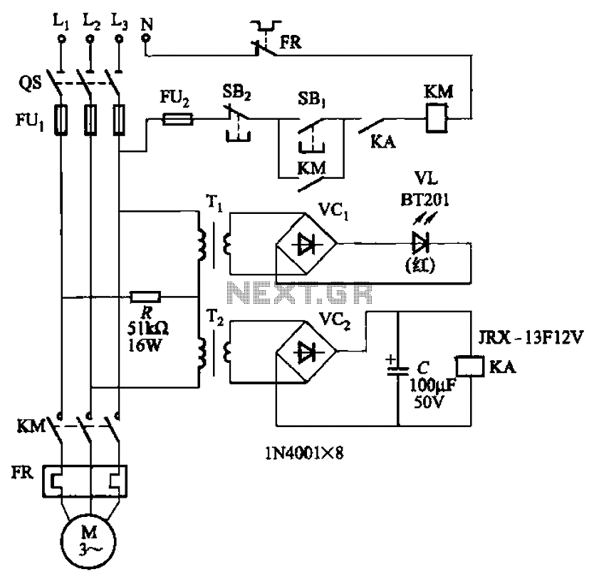
Allowing only one-way operation of the motor-controlled circuit 2
The circuit depicted in Figure 3-92 employs a dual-phase sequence protection relay for sensing. When the power supply exhibits a positive phase sequence (U, V, W), the relay KA is activated. If the power supply maintains the correct phase sequence,...
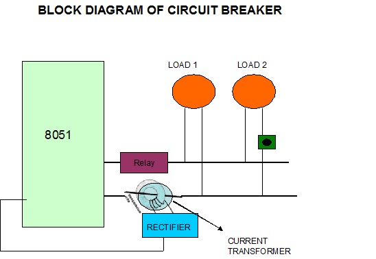
electronic circuit breaker
A circuit breaker is an automatically operated electrical switch designed to protect an electrical circuit from damage caused by overload or short circuit. Its basic function is to detect a fault condition and, by interrupting continuity, immediately discontinue electrical flow....
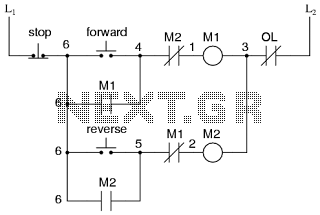
Motor control circuit for forward and reverse phase induction
This is the power diagram for motor forward and reverse operation. To change the motor direction, one polarity must be altered, for example, changing R to S. For detailed information, please refer to the following.
The described power diagram illustrates a...
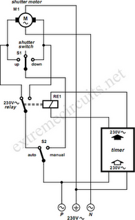
To Automate Rolling Shutter Motor
To automate the opening and closing of a rolling shutter using a time-controlled switch, additional wiring will be necessary.
To implement an automated system for a rolling shutter, a time-controlled switch can be utilized to manage the operation of the shutter....
motor timer
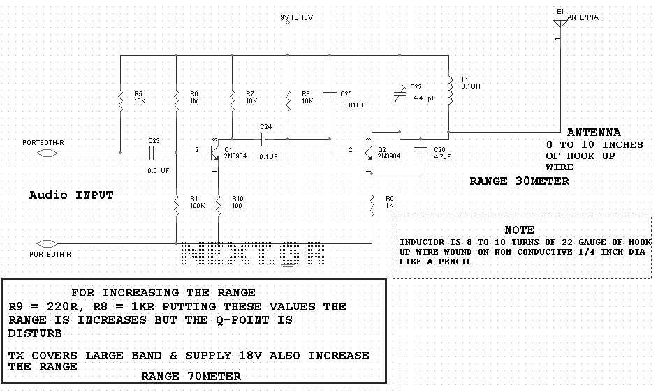
The primary concept is to rotate the motor slightly every 15 seconds. A monofilament line conveys the motion to the ornament, which is wound by the motor and gradually unwinds as the ornament turns. The charging circuit includes a 1...
2 Way Switch Wire Electrical
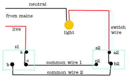
The following circuit illustrates a 2-way switch wiring electrical circuit diagram. Features include the ability to turn on the lights using switch S1, which has three terminals.
The 2-way switch circuit is commonly used in residential and commercial applications to control...