


Motor winding circuit diagram of the current imbalance dried
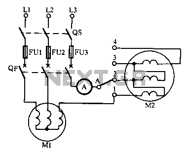
Description: Drying the motor winding circuit current imbalance. Below is a circuit diagram of the motor winding current imbalance drying.
The circuit for drying motor winding current imbalance is designed to address the issue of uneven current distribution across the windings of an electric motor. This imbalance can lead to overheating, reduced efficiency, and potential damage to the motor. The schematic typically includes components such as resistors, capacitors, diodes, and a microcontroller or relay for monitoring and control.
In the circuit, current sensors are strategically placed to measure the current flowing through each winding. These sensors provide real-time feedback to the control unit, which processes the data to determine if any windings are receiving an unequal amount of current. If an imbalance is detected, the control unit activates a drying sequence.
The drying process usually involves applying a controlled voltage to the affected winding(s) to facilitate the evaporation of moisture that may have accumulated due to environmental factors. This is often achieved through the use of resistive heating elements that can be integrated into the circuit. The resistors are chosen based on their power rating to ensure they can handle the necessary load without overheating.
Diodes may be included to protect the circuit from reverse voltage spikes, which can occur when the motor is switched off or during transient conditions. Additionally, capacitors can be used to smooth out voltage fluctuations and improve the overall stability of the circuit.
The final output of the circuit is a balanced current distribution across the motor windings, ensuring optimal performance and longevity of the motor. Proper design and implementation of this circuit are crucial for maintaining the reliability of electric motors in various applications.Drying the motor winding circuit current imbalance Below is a circuit diagram of the motor winding current imbalance drying:
The circuit for drying motor winding current imbalance is designed to address the issue of uneven current distribution across the windings of an electric motor. This imbalance can lead to overheating, reduced efficiency, and potential damage to the motor. The schematic typically includes components such as resistors, capacitors, diodes, and a microcontroller or relay for monitoring and control.
In the circuit, current sensors are strategically placed to measure the current flowing through each winding. These sensors provide real-time feedback to the control unit, which processes the data to determine if any windings are receiving an unequal amount of current. If an imbalance is detected, the control unit activates a drying sequence.
The drying process usually involves applying a controlled voltage to the affected winding(s) to facilitate the evaporation of moisture that may have accumulated due to environmental factors. This is often achieved through the use of resistive heating elements that can be integrated into the circuit. The resistors are chosen based on their power rating to ensure they can handle the necessary load without overheating.
Diodes may be included to protect the circuit from reverse voltage spikes, which can occur when the motor is switched off or during transient conditions. Additionally, capacitors can be used to smooth out voltage fluctuations and improve the overall stability of the circuit.
The final output of the circuit is a balanced current distribution across the motor windings, ensuring optimal performance and longevity of the motor. Proper design and implementation of this circuit are crucial for maintaining the reliability of electric motors in various applications.Drying the motor winding circuit current imbalance Below is a circuit diagram of the motor winding current imbalance drying:
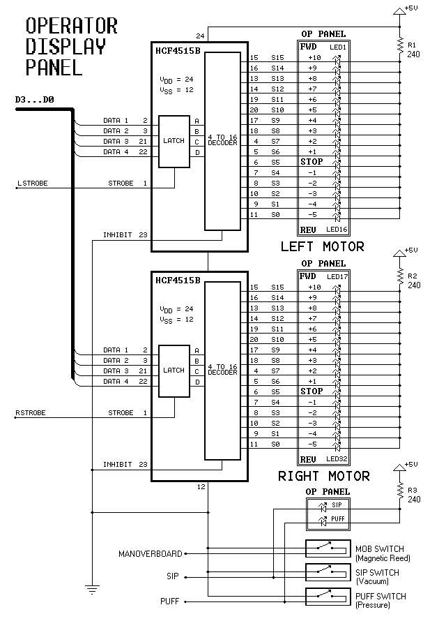
Dual-Motor SIP&PUFF Controlled Kayak System
The YouTube video below demonstrates the quick and easy setup of the system at the launch site.
The provided description indicates a focus on the efficiency of system installation at a launch site, as showcased in a YouTube video. In an...
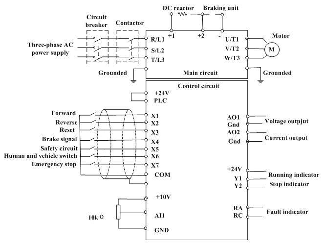
motor control inverter (AC drive) in mine industry
Motor control, energy efficiency of inverter (AC drive) selection, and parameters setting guidance in the mining industry: vector control, open loop or closed loop control, with energy braking unit or energy feedback unit.
In the context of motor control for the...
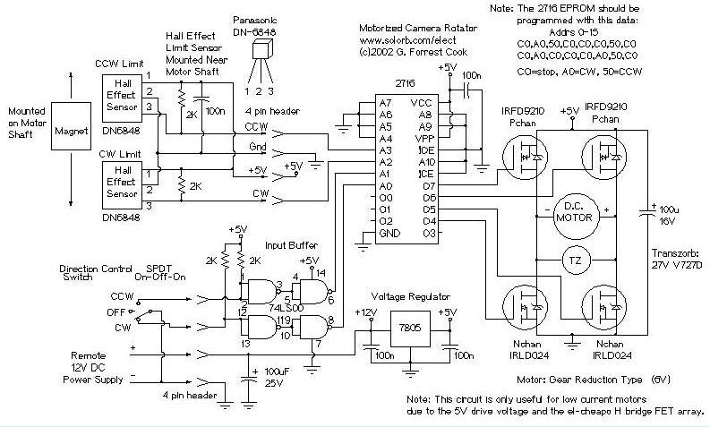
Motorized Video Camera Mount
The camera rotator circuit utilizes a 2716 EPROM to store a logic value table that governs the motor driver (H-bridge) circuit. The schematic illustrates the EPROM data. By employing the EPROM, a significant number of discrete gates are eliminated. The...
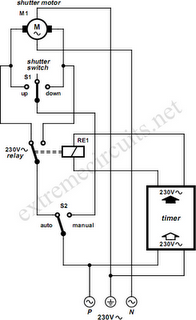
To Automate Rolling Shutter Motor
To automate the opening and closing of a rolling shutter using a time-controlled switch, additional wiring will be necessary.
To implement an automated system for a rolling shutter, a time-controlled switch can be utilized to manage the operation of the shutter....
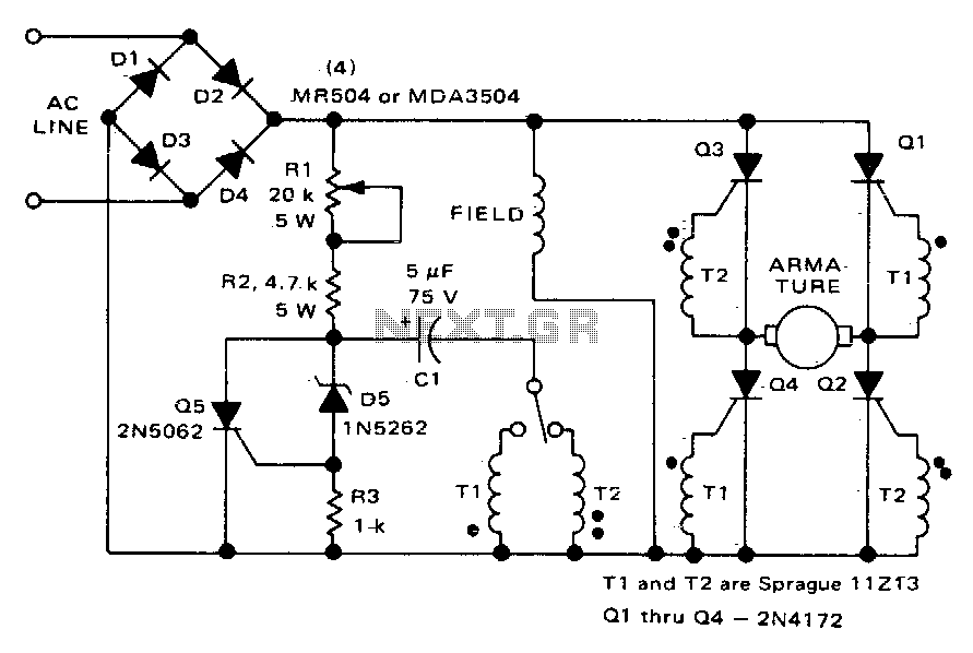
Direction and speed control
This circuit functions similarly to the one depicted in Fig. 57-4. The key differences include the placement of the field across the rectified supply and the armature being positioned within the SCR bridge. Therefore, the field current is unidirectional while...
Gray Projects
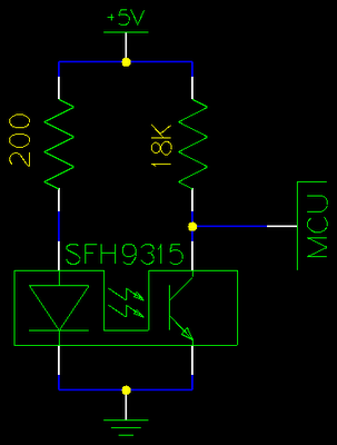
After learning to operate the device, it became evident that inertia posed a significant challenge. The constructed system is notably heavy, making it difficult to initiate motor operation at full speed. Despite having some understanding of physics, practical experience is...
motor timer
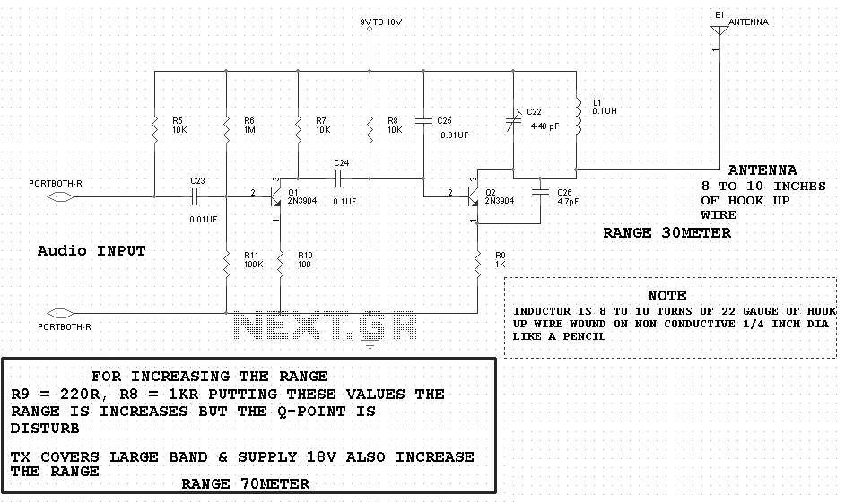
The primary concept is to rotate the motor slightly every 15 seconds. A monofilament line conveys the motion to the ornament, which is wound by the motor and gradually unwinds as the ornament turns. The charging circuit includes a 1...
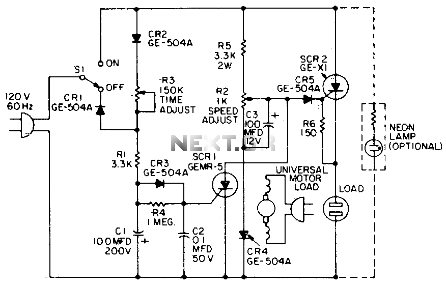
Universal motor control
When the time delay expires, SCR1 conducts and removes the gate signal from SCR2, which stops the motor. Both the time delay and motor speed are adjustable by potentiometers R2 and R3. If heavier motor loads are anticipated, use the...
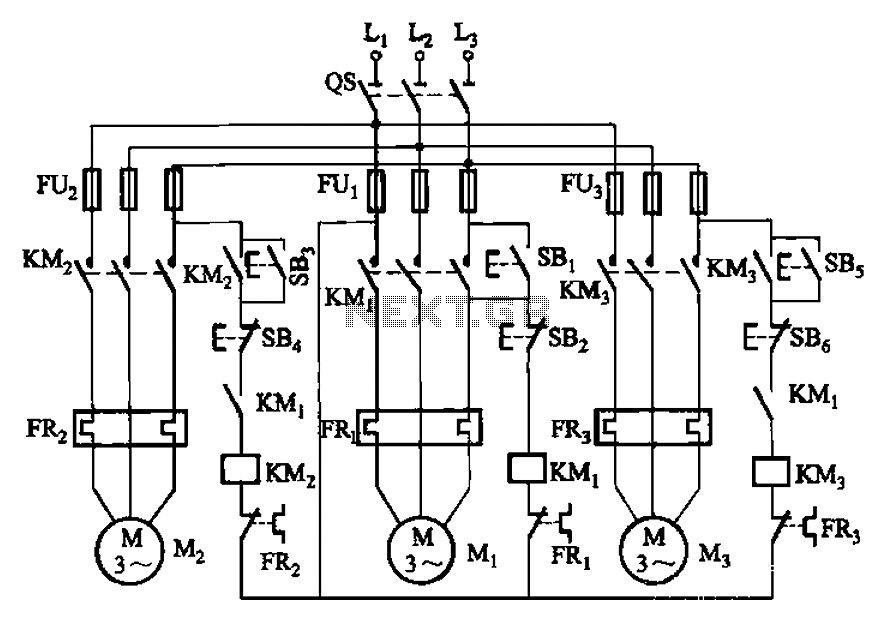
Three motor control circuit start and stop sequence requirements
The circuit shown in Figure 3-89 illustrates a system where starting motor M1 allows motors M2 and M3 to initiate operation. Upon shutdown, motor Mz can be stopped first; however, once motor M1 is stopped (by pressing switch SB2), motors...