


NJM2670 NJM2670 DUAL H BRIDGE DRIVER
#H bridge
#stepper motor
#driver
#microstepping
#dual DAC
#motor driver
#NJM2670
#NJM3772
#NJU39610
#switching control
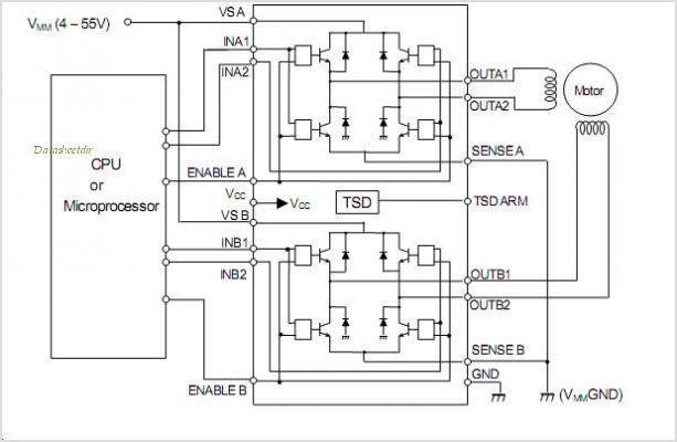
Description: The NJM3772 is a stepper motor driver circuit specifically designed for microstepping applications in conjunction with the compatible dual DAC (Digital-to-Analog Converter) NJU39610. The NJM3772 features a clock oscillator that is shared between both driver channels, a set of comparators, and flip-flops for implementing switching control. It also includes two H-bridges with internal recirculation diodes. The voltage supply requirements are +5 V for logic and +10 to +45 V for the motor. The maximum output current is 1000 mA per channel.
The NJM3772 stepper motor driver is engineered to provide precise control over stepper motors in applications requiring high resolution and smooth operation. The integration of a shared clock oscillator allows for synchronized operation of the dual driver channels, which is crucial for achieving microstepping functionality. This feature enables the stepper motor to operate at fractional steps, enhancing the positioning accuracy and reducing vibration compared to full-step driving methods.
The inclusion of comparators and flip-flops in the NJM3772 design facilitates the implementation of advanced switching control strategies. These components work together to ensure that the motor phases are energized in a manner that optimizes torque and minimizes power losses. The internal H-bridges are capable of bidirectional control of the motor phases, allowing for both forward and reverse motion. Furthermore, the presence of internal recirculation diodes protects the circuit from back EMF generated by the motor, enhancing reliability and longevity.
The voltage supply requirements of +5 V for logic and +10 to +45 V for motor operation provide flexibility in system design, accommodating a wide range of stepper motors with varying voltage ratings. The maximum output current of 1000 mA per channel ensures that the NJM3772 can drive most small to medium-sized stepper motors effectively, making it suitable for applications in robotics, CNC machinery, and various automation systems.
Overall, the NJM3772 stepper motor driver, when paired with the NJU39610 DAC, offers a robust solution for microstepping applications, delivering precision control and reliable performance in demanding environments. Its design features and specifications make it a valuable component in the field of motion control and automation.The NJM3772 is a stepper motor driverwhich circuit is especially developed for use in microstepping applications in conjunction with the matching dual DAC (Digital-to-Analog Converter) NJU39610. The NJM3772 contains a Clock oscillatorwhich is common for both driver channelsa set of Comparators and Flip-Flops implementing the switching controland t
wo H-bridges with internal recirculation Diodes Voltage supply requirements are +5 V for Logic and +10 to +45V for the motor. Maximum output current is 1000mA per channel.
The NJM3772 stepper motor driver is engineered to provide precise control over stepper motors in applications requiring high resolution and smooth operation. The integration of a shared clock oscillator allows for synchronized operation of the dual driver channels, which is crucial for achieving microstepping functionality. This feature enables the stepper motor to operate at fractional steps, enhancing the positioning accuracy and reducing vibration compared to full-step driving methods.
The inclusion of comparators and flip-flops in the NJM3772 design facilitates the implementation of advanced switching control strategies. These components work together to ensure that the motor phases are energized in a manner that optimizes torque and minimizes power losses. The internal H-bridges are capable of bidirectional control of the motor phases, allowing for both forward and reverse motion. Furthermore, the presence of internal recirculation diodes protects the circuit from back EMF generated by the motor, enhancing reliability and longevity.
The voltage supply requirements of +5 V for logic and +10 to +45 V for motor operation provide flexibility in system design, accommodating a wide range of stepper motors with varying voltage ratings. The maximum output current of 1000 mA per channel ensures that the NJM3772 can drive most small to medium-sized stepper motors effectively, making it suitable for applications in robotics, CNC machinery, and various automation systems.
Overall, the NJM3772 stepper motor driver, when paired with the NJU39610 DAC, offers a robust solution for microstepping applications, delivering precision control and reliable performance in demanding environments. Its design features and specifications make it a valuable component in the field of motion control and automation.The NJM3772 is a stepper motor driverwhich circuit is especially developed for use in microstepping applications in conjunction with the matching dual DAC (Digital-to-Analog Converter) NJU39610. The NJM3772 contains a Clock oscillatorwhich is common for both driver channelsa set of Comparators and Flip-Flops implementing the switching controland t
wo H-bridges with internal recirculation Diodes Voltage supply requirements are +5 V for Logic and +10 to +45V for the motor. Maximum output current is 1000mA per channel.
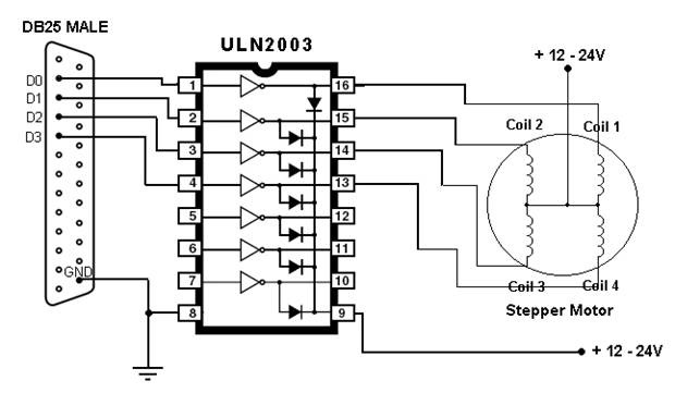
Computer Controlled Stepper Motor
This article outlines the process of connecting a stepper motor to a computer's parallel port and writing code to control it using the scroll wheel of a mouse. For those unfamiliar with stepper motors, this project offers an engaging introduction....
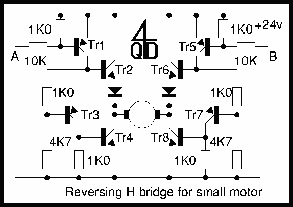
H bridge switch for small motors
Two inputs, A and B, control the bridge. With both high (or open circuit) both ends of the motor are connected to 0v. Connect A low and Tr2 turns on causing the motor to go forward. Connect B low and...
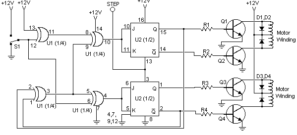
Stepper Motor Controller
I found this circuit in my files. I don't know where it came from, but it looks like I photocopied it from somewhere years ago. I have been told that it came from "The Robot Builder's Bonanza", by Gordan McComb....
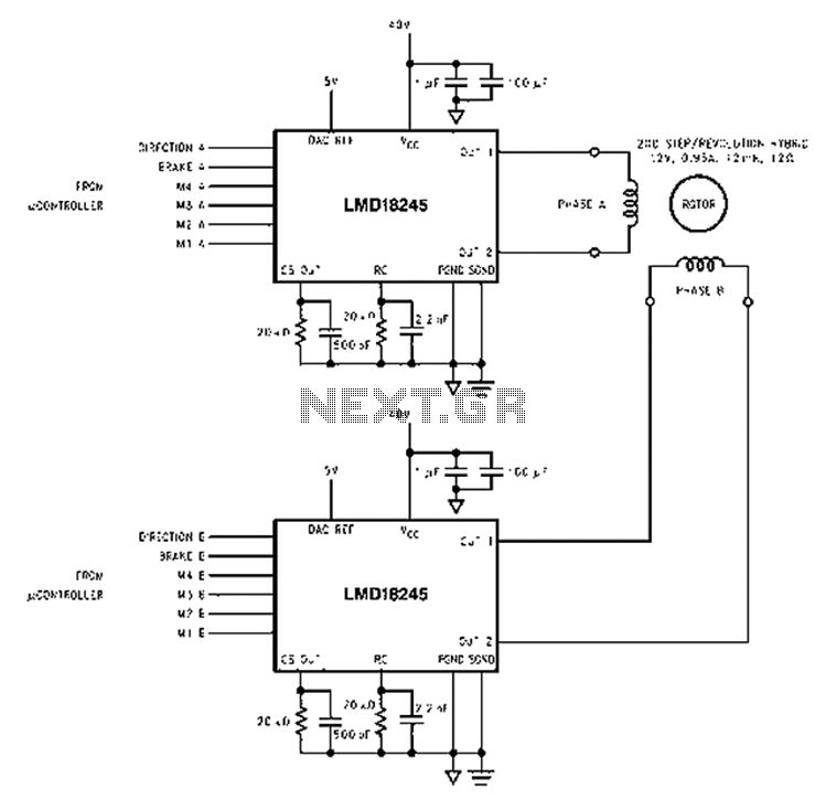
Based LMD18245 bipolar stepper motor control circuit diagram
An innovative current detection method eliminates the power loss associated with the sense resistor in series with the motor. A 4-digit analog converter (DAC) facilitates digital control of the motor current path, simplifying the implementation of full, half, and micro-stepping...

Precise Camera Panning with Stepper Motors
The prototype circuit board utilized an external LCD display that received commands through an RS-232 interface. While this setup functioned adequately, programming it was cumbersome. Consequently, the circuit board was revised to support a directly attached LCD display. The image...

This paper describes the process by which a control circuit for a stepper-motor was designed
This document outlines the design process of a control circuit for a stepper motor. Given the characteristics of the stepper motor, the control circuit was developed as a state machine that transitions through four output states depending on two input...
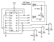
Design a Unipolar Stepper Motor Controller/Driver and
A motor coil requires controllers to adjust its position and speed. A motor driver is necessary to amplify the low output current from a controller to a larger current required by the motor. The following article describes how to design...
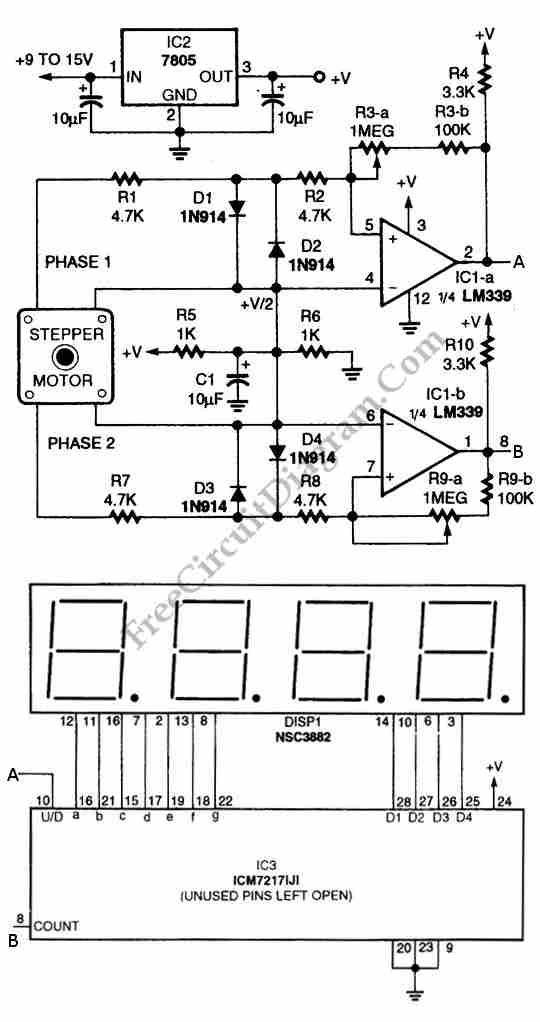
Digital Encoder Circuit Using Stepper Motor
The circuit illustrated in the schematic diagram below allows for the visualization of the direction and shaft rotation of a stepper motor on an LED display. Instead of employing a digital rotation encoder as an input, this circuit utilizes a...
Stepper Motor Controller
I found this circuit in my files. I don't know where it came from, but it looks like I photocopied it from somewhere years ago. I have been told that it came from "The Robot Builder's Bonanza", by Gordan McComb....