


One-way operation of the brake circuit reverse
#brake circuit
#speed relay
#electric engine
#reverse operation
#relay
#motor speed
#control circuit
#industrial
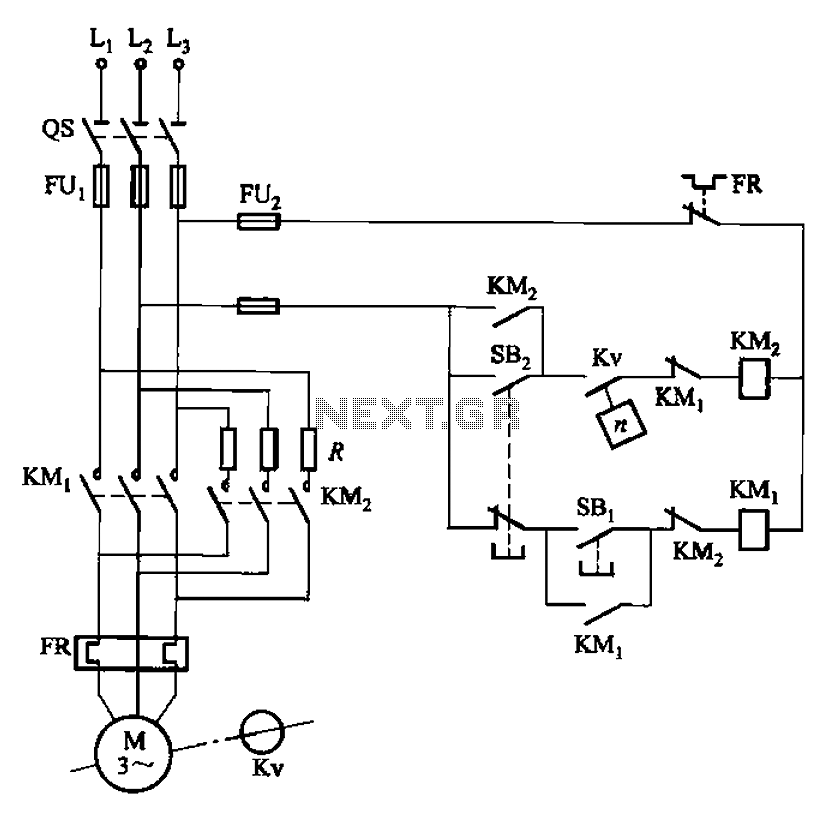
Description: The circuit depicted in Figure 3-124 operates without an intermediate relay. Kv serves as the speed relay, activating when the electric motor speed exceeds 120 r/min while the contact is closed. If the speed drops below 100 r/min, the contacts open, leading to a shutdown. When this occurs, the KMi contact releases, and KMz pulls in to initiate plug braking. As the speed falls below 100 r/min, the Kv contacts open, resulting in KM2 releasing and concluding the braking process, which lasts approximately 1 to 3 seconds. The braking resistor R is included to limit the reverse current during braking and can also be connected to only two phases.
The circuit design incorporates a speed relay (Kv) that plays a crucial role in monitoring and controlling the operational speed of an electric motor. The functionality is contingent upon the motor speed, with specific thresholds set at 120 r/min and 100 r/min. When the motor operates above 120 r/min, the relay remains engaged, allowing the system to function normally. However, once the speed drops below 100 r/min, the Kv relay disengages, which triggers a series of actions to ensure safe operation.
Upon disengagement of the Kv relay, the KMi contact is released, which signifies that the motor should cease operation. Concurrently, KMz is activated to engage plug braking, a method that reverses the motor phase connections to rapidly decelerate the motor. This process is essential for applications requiring a quick stop to prevent damage or ensure safety.
The circuit includes a braking resistor (R) that serves to limit the reverse current generated during the braking phase. This is critical to protect the circuit components from potential damage due to excessive current. The resistor can be connected to only two of the three phases, providing flexibility in the circuit design while maintaining effective braking performance.
Once the motor speed has decreased to below 100 r/min, the Kv contacts open, which leads to the release of KM2. This action signifies the conclusion of the braking process, which is designed to last between 1 to 3 seconds, allowing for a controlled and safe stopping procedure. Overall, the circuit is designed to enhance the operational safety and efficiency of electric motor systems by integrating speed monitoring and responsive braking mechanisms. Circuit shown in Figure 3-124. The line does not use an intermediate relay. Figure, Kv is the speed relay, when the electric engine speed is greater than 120r/min when the cont act is closed, less than 100 r/min, the contacts open. Shutdown, contact KMi release put, KMz pull, plug braking. When the speed is lower than lOOr/min, Kv contacts open. KM2 release, the braking process ends (about 1 ~ 3s). Access braking resistor R purpose is to limit the reverse current brake. R can also be connected to only two phases.
The circuit design incorporates a speed relay (Kv) that plays a crucial role in monitoring and controlling the operational speed of an electric motor. The functionality is contingent upon the motor speed, with specific thresholds set at 120 r/min and 100 r/min. When the motor operates above 120 r/min, the relay remains engaged, allowing the system to function normally. However, once the speed drops below 100 r/min, the Kv relay disengages, which triggers a series of actions to ensure safe operation.
Upon disengagement of the Kv relay, the KMi contact is released, which signifies that the motor should cease operation. Concurrently, KMz is activated to engage plug braking, a method that reverses the motor phase connections to rapidly decelerate the motor. This process is essential for applications requiring a quick stop to prevent damage or ensure safety.
The circuit includes a braking resistor (R) that serves to limit the reverse current generated during the braking phase. This is critical to protect the circuit components from potential damage due to excessive current. The resistor can be connected to only two of the three phases, providing flexibility in the circuit design while maintaining effective braking performance.
Once the motor speed has decreased to below 100 r/min, the Kv contacts open, which leads to the release of KM2. This action signifies the conclusion of the braking process, which is designed to last between 1 to 3 seconds, allowing for a controlled and safe stopping procedure. Overall, the circuit is designed to enhance the operational safety and efficiency of electric motor systems by integrating speed monitoring and responsive braking mechanisms. Circuit shown in Figure 3-124. The line does not use an intermediate relay. Figure, Kv is the speed relay, when the electric engine speed is greater than 120r/min when the cont act is closed, less than 100 r/min, the contacts open. Shutdown, contact KMi release put, KMz pull, plug braking. When the speed is lower than lOOr/min, Kv contacts open. KM2 release, the braking process ends (about 1 ~ 3s). Access braking resistor R purpose is to limit the reverse current brake. R can also be connected to only two phases.
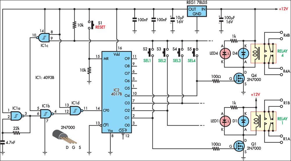
Pushbutton Relay Selector
This circuit is designed for use in a hi-fi showroom, allowing a selection of speakers to be connected to a stereo amplifier for comparative purposes. It can also serve similar applications where only one device from an array needs to...
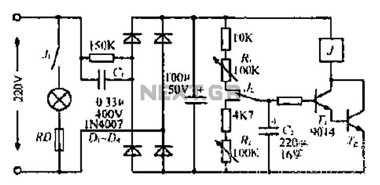
Lantern making use of a relay control circuit
220V mains electricity is sent through a 0.33 µF capacitor (Ci) and a 50 kΩ resistive drop. A bridge rectifier composed of diodes D1 to D4 converts the AC voltage to DC. After passing through a 100 µF capacitor for...
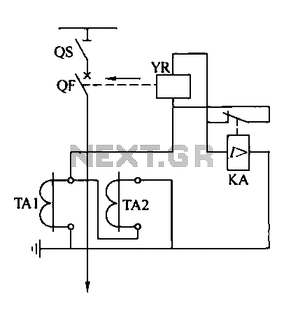
Relay protection circuit
Operating power protection devices can be categorized into two types: DC power supply operation and AC operation. AC operating power is favored due to its lower investment costs, simpler operation, and reliable secondary circuit maintenance, making it widely used in...
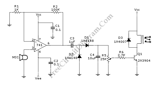
Sound-Controlled Relay
This is a relay circuit that detects the presence of sound to activate the relay. This sound-controlled relay can be utilized as a voice-operated switch or for controlling lights.
The sound-activated relay circuit typically employs a microphone or a sound sensor...
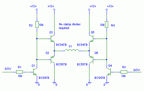
What type of protector to use
The PE014A12 relay from Tyco Electronics features a single coil that requires a positive voltage to activate and a negative voltage to deactivate.
The PE014A12 relay is a single-coil electromagnetic relay designed for applications requiring a simple on/off switching mechanism. The...
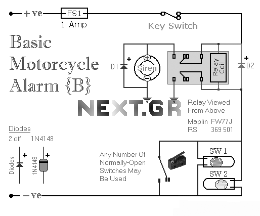
Two Simple Relay Based Motorcycle Alarms
Two simple relay-based motorcycle alarm circuits. These are easy to build and can be used to protect motorcycles, but they also have many other applications. If relays with 6-volt coils are used...
The motorcycle alarm circuits described consist of two basic...
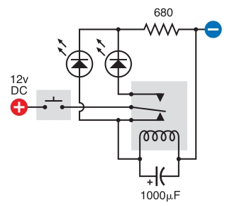
relay circuit
The intended result is for the relay to oscillate and the LEDs to flash when the button is pressed. However, when the button is pressed, the leftmost LED lights constantly, and nothing else happens. There is voltage across the left...
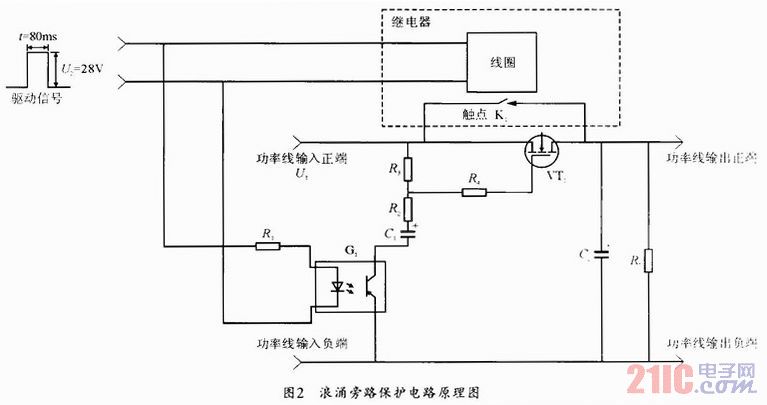
bypass which improves the ability to resist surging of relay contact
During the power-up of the apparatus, the capacitor is primarily responsible for the emergence of surge current. The schematic diagram of the principle is illustrated in Fig. 1. After K1 closes, the capacitor begins to charge, assuming that the direct...
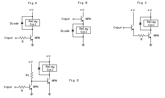
Controlling a relay with a digital logic level circuit
The schematic below illustrates four methods of controlling a relay with a digital logic signal. Figure A can be used in most cases where the relay coil requires 100 mA or less and the input current is 2 milliamps or...