


PQS1 series magnetic disk control panning control circuit
#master controller
#magnetic disk
#bridge crane
#hoist lifting
#control panel
#PQS1 series
#industrial control
#automation
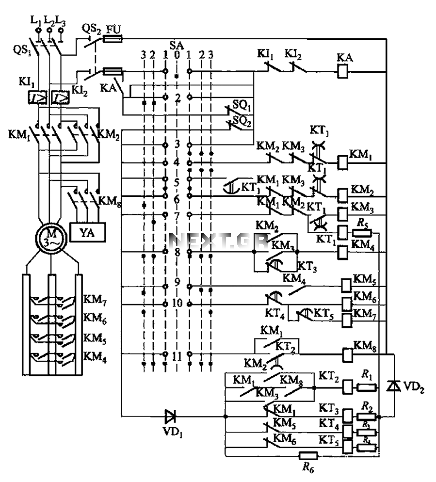
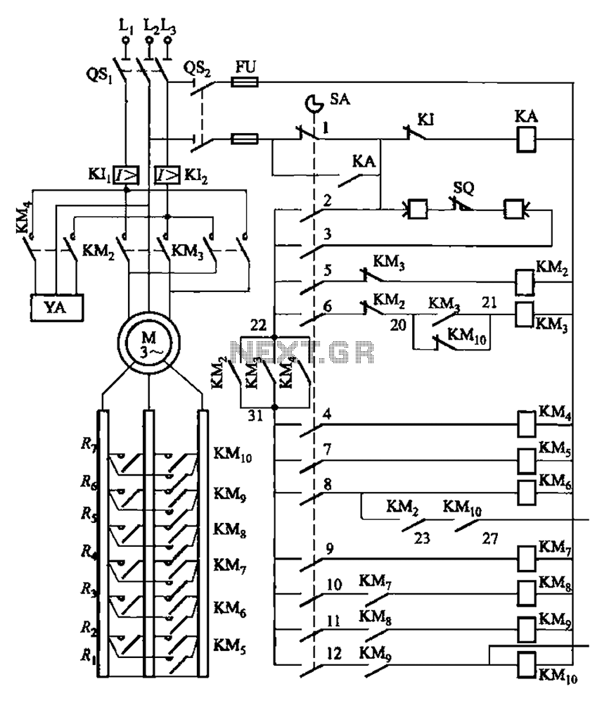
Description: The system involves a master controller and a PQS1 Series Magnetic control panel, which includes a control circuit designed to manage the bridge crane hoist lifting mechanism. The master controller handle SA features seven positions: alongside the zero position, it offers three lifting gear settings that allow for three different lifting speeds. Additionally, there are three drop blocks, with the second block designated for single-phase brake operations. The first three blocks are used for forced descent, activated when the weight transitions to a declining system. The first stop is only engaged when the first block is pulled from the first block 2 or 3, allowing for braking during descent. The zero position activates a parking brake when the first action occurs, with a motor delay of 0.65 seconds to prevent power-induced stopping that could lead to heavy slip of the hook. The relay KTi has a pull delay of 0.11 to 0.16 seconds and an off delay of 0.15 to 0.2 seconds, primarily to extend contact access time and prevent phase short circuits.
The described system integrates a master controller with a PQS1 Series Magnetic control panel, which serves as the central unit for managing the operational parameters of the bridge crane hoist. The control circuit is meticulously designed to facilitate precise control over the lifting and lowering mechanisms of the crane.
The master controller handle SA, with its seven distinct positions, provides operators with the flexibility to select from three different lifting speeds, enhancing operational efficiency based on the load requirements. The zero position serves as a safety feature, engaging the parking brake to secure the crane when not in operation.
The three drop blocks are critical for managing the descent of the load. The second block is specifically intended for single-phase braking, allowing for controlled lowering of the load. The forced descent feature, activated by the first three blocks, ensures that the crane can safely lower heavy loads under specific conditions, thereby preventing uncontrolled descent.
The timing mechanisms, including the motor delay of 0.65 seconds and the relay KTi's pull and off delays, are essential for ensuring the safety and reliability of the system. The motor delay prevents abrupt stopping that could lead to a heavy slip of the hook, while the relay delays serve to extend the contact access time, effectively minimizing the risk of phase short circuits. These features collectively enhance the operational safety and efficiency of the bridge crane hoist, making it suitable for various industrial applications where precise load handling is crucial. By master controller and PQS1 Series Magnetic control panel consisting of a control circuit for controlling the bridge crane hoist lifting mechanism of control. Master controll er handle SA has seven positions: In addition to the zero position, there are three lifting gear, lift speed can be obtained in three different degrees; there are three drop block, the second block for the single-phase brake down first 3 block is forced down if it is the weight of the transition to a system for generating motion decline; first stop only when pulled from the first block of the first block 2, 3, in order to pull down the brake for fall, nowhere else. Zero parking brake when YA first action, the motor delay o. 65s after power to prevent stopping power generated with heavy slip hook. Commutation of the relay KTi pull delay is 0.11N0.16 s, off delay is 0.15 ~ 0. 2s, the main purpose is to extend contacts for access time, to avoid phase short circuit.
The described system integrates a master controller with a PQS1 Series Magnetic control panel, which serves as the central unit for managing the operational parameters of the bridge crane hoist. The control circuit is meticulously designed to facilitate precise control over the lifting and lowering mechanisms of the crane.
The master controller handle SA, with its seven distinct positions, provides operators with the flexibility to select from three different lifting speeds, enhancing operational efficiency based on the load requirements. The zero position serves as a safety feature, engaging the parking brake to secure the crane when not in operation.
The three drop blocks are critical for managing the descent of the load. The second block is specifically intended for single-phase braking, allowing for controlled lowering of the load. The forced descent feature, activated by the first three blocks, ensures that the crane can safely lower heavy loads under specific conditions, thereby preventing uncontrolled descent.
The timing mechanisms, including the motor delay of 0.65 seconds and the relay KTi's pull and off delays, are essential for ensuring the safety and reliability of the system. The motor delay prevents abrupt stopping that could lead to a heavy slip of the hook, while the relay delays serve to extend the contact access time, effectively minimizing the risk of phase short circuits. These features collectively enhance the operational safety and efficiency of the bridge crane hoist, making it suitable for various industrial applications where precise load handling is crucial. By master controller and PQS1 Series Magnetic control panel consisting of a control circuit for controlling the bridge crane hoist lifting mechanism of control. Master controll er handle SA has seven positions: In addition to the zero position, there are three lifting gear, lift speed can be obtained in three different degrees; there are three drop block, the second block for the single-phase brake down first 3 block is forced down if it is the weight of the transition to a system for generating motion decline; first stop only when pulled from the first block of the first block 2, 3, in order to pull down the brake for fall, nowhere else. Zero parking brake when YA first action, the motor delay o. 65s after power to prevent stopping power generated with heavy slip hook. Commutation of the relay KTi pull delay is 0.11N0.16 s, off delay is 0.15 ~ 0. 2s, the main purpose is to extend contacts for access time, to avoid phase short circuit.
automatic pet feeder
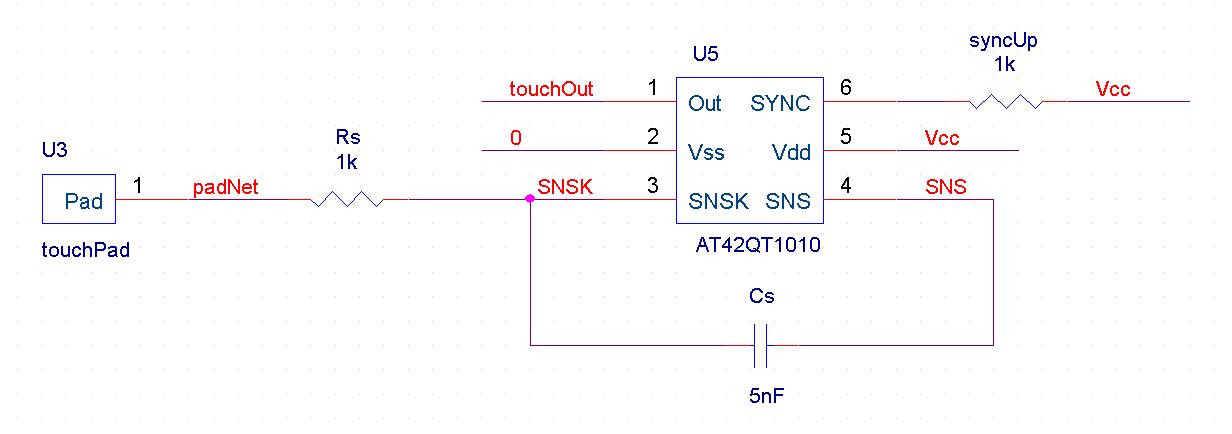
An automatic feeder dispenses food based on the activation of a series of buttons, which interface with a system controller and a food dispenser. The system is designed for intelligent processing of inputs and outputs, allowing dynamic configuration of button...
PQY2 series magnetic disk control panning control circuit
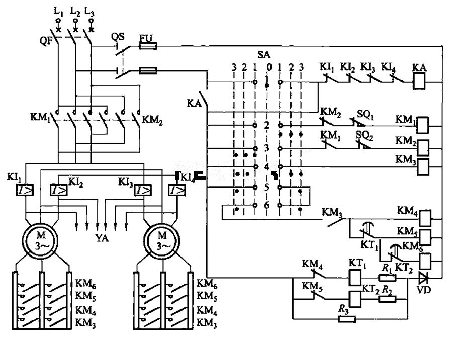
The LK16-5/31 type master controller and PQY2 Series Magnetic control panel comprise a control circuit. The PQY2 series control panel, along with the magnetic PQY1 control panel, features a similar control circuit. The electrical components are fundamentally the same; however,...
Coop automatic controller circuit diagram
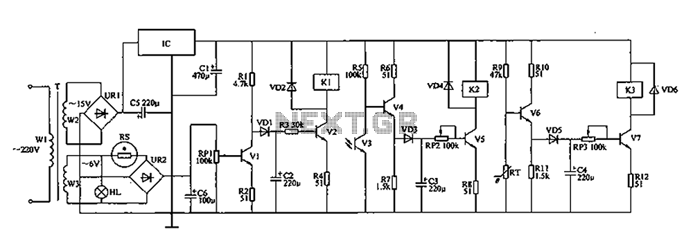
The automatic controller for a chicken coop is designed to automatically regulate light, temperature, and humidity, thereby enhancing egg production and survival rates of chickens. This device is intended for specialized poultry households in rural areas. The circuit operates through...
PQR10A type magnetic disk control panning control circuit
The system is managed by the master controller LKl-12/90 and a magnetic disk control unit PQR10A, which includes a control circuit. The cam control device SA is responsible for contact closure, as indicated in Table 8-5. The main electrical components...

Objects in Flux
The Open Source Automation project is a free automation software that operates on Windows and does not require programming for setup. It features a user-friendly graphical interface and includes unique functionalities that are not typically found in high-end security and...