


PWM Motor/Light Controller
#PWM
#motor controller
#light controller
#N Channel FET
#P Channel FET
#12V
#high side
#low side
#common ground
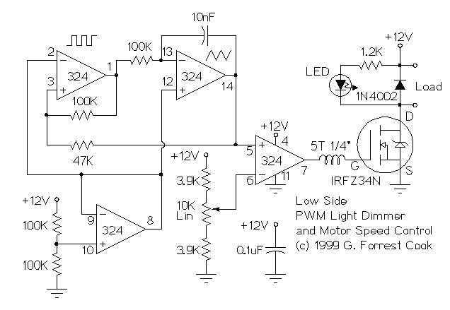
Description: These two schematics are variations on another PWM circuit that I designed. The diagrams are for 12V operation only and there are high side (common ground) and low side (common +12V) versions. The low side version of the circuit uses an N Channel FET, the high side version of the circuit uses a P Channel FET. N Channel devices tend to handle more current than P Channel devices, they are also less expensive. The high side version of the circuit is useful when one side of the load has to be grounded. More: This circuit can switch a fairly high amount of current, an IRFZ34N MOSFET can handle over 35 Amps if connected to a proper heat sink. Higher power FETs, such as the IRFZ48N or IRF1010Z can be substituted if even larger currents are required. It is also p
The described circuit consists of two distinct configurations intended for PWM (Pulse Width Modulation) control, specifically designed for 12V applications. The configurations include a low-side switching arrangement utilizing an N-channel MOSFET and a high-side switching arrangement utilizing a P-channel MOSFET.
In the low-side configuration, the N-channel MOSFET is connected between the load and ground. This arrangement allows for efficient current handling due to the inherent characteristics of N-channel devices, which typically offer lower on-resistance and higher current capacity compared to P-channel devices. The IRFZ34N MOSFET, capable of handling over 35 Amps, is recommended for this configuration, especially when paired with an adequate heat sink to manage thermal performance. For applications requiring even higher current capabilities, alternative MOSFETs such as the IRFZ48N or IRF1010Z may be utilized.
Conversely, the high-side configuration connects the P-channel MOSFET between the power supply (12V) and the load. This setup is particularly beneficial when it is necessary to ground one side of the load, which is a common requirement in various applications. Although P-channel devices are generally more expensive and less efficient in terms of current handling, they serve a critical role in circuits where high-side switching is essential.
Both configurations are designed to operate under PWM control, allowing for efficient modulation of power delivered to the load. The choice between high-side and low-side configurations depends on the specific requirements of the application, including load characteristics and the necessity of grounding one side of the load. Proper selection and implementation of the MOSFETs, along with appropriate thermal management, are crucial for ensuring reliable operation of these PWM circuits.These two schematics are variations on another PWM circuit that I designed. The diagrams are for 12V operation only and there are high side (common ground) and low side (common +12V) versions. The low side version of the circuit uses an N Channel FET, the high side version of the circuit uses a P Channel FET.
N Channel devices tend to handle more current than P Channel devices, they are also less expensive. The high side version of the circuit is useful when one side of the load has to be grounded. This circuit can switch a fairly high amount of current, an IRFZ34N MOSFET can handle over 35 Amps if connected to a proper heat sink. Higher power FETs, such as the IRFZ48N or IRF1010Z can be substituted if even larger currents are required.
It is also p
The described circuit consists of two distinct configurations intended for PWM (Pulse Width Modulation) control, specifically designed for 12V applications. The configurations include a low-side switching arrangement utilizing an N-channel MOSFET and a high-side switching arrangement utilizing a P-channel MOSFET.
In the low-side configuration, the N-channel MOSFET is connected between the load and ground. This arrangement allows for efficient current handling due to the inherent characteristics of N-channel devices, which typically offer lower on-resistance and higher current capacity compared to P-channel devices. The IRFZ34N MOSFET, capable of handling over 35 Amps, is recommended for this configuration, especially when paired with an adequate heat sink to manage thermal performance. For applications requiring even higher current capabilities, alternative MOSFETs such as the IRFZ48N or IRF1010Z may be utilized.
Conversely, the high-side configuration connects the P-channel MOSFET between the power supply (12V) and the load. This setup is particularly beneficial when it is necessary to ground one side of the load, which is a common requirement in various applications. Although P-channel devices are generally more expensive and less efficient in terms of current handling, they serve a critical role in circuits where high-side switching is essential.
Both configurations are designed to operate under PWM control, allowing for efficient modulation of power delivered to the load. The choice between high-side and low-side configurations depends on the specific requirements of the application, including load characteristics and the necessity of grounding one side of the load. Proper selection and implementation of the MOSFETs, along with appropriate thermal management, are crucial for ensuring reliable operation of these PWM circuits.These two schematics are variations on another PWM circuit that I designed. The diagrams are for 12V operation only and there are high side (common ground) and low side (common +12V) versions. The low side version of the circuit uses an N Channel FET, the high side version of the circuit uses a P Channel FET.
N Channel devices tend to handle more current than P Channel devices, they are also less expensive. The high side version of the circuit is useful when one side of the load has to be grounded. This circuit can switch a fairly high amount of current, an IRFZ34N MOSFET can handle over 35 Amps if connected to a proper heat sink. Higher power FETs, such as the IRFZ48N or IRF1010Z can be substituted if even larger currents are required.
It is also p
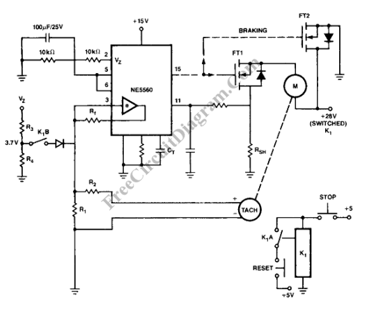
Closed Loop PWM Motor Control
Closed loop motor control is utilized for maintaining constant speed in motor operations. This means that the motor's speed is regulated to remain steady.
Closed loop motor control systems, commonly referred to as servo control systems, are essential in applications requiring...
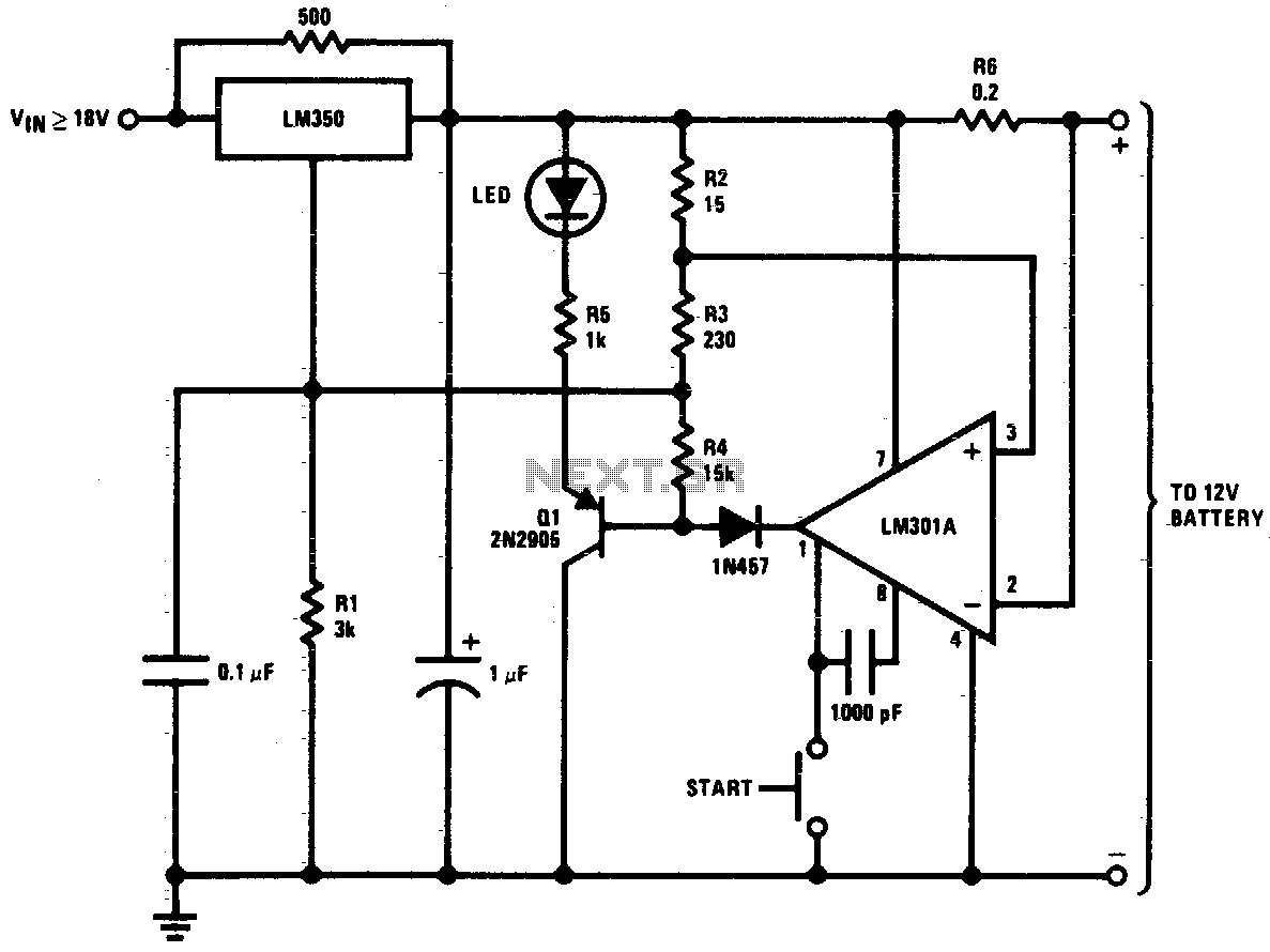
12 V battery charger
This circuit is a high-performance charger for gelled electrolyte lead-acid batteries. The charger quickly recharges the battery and automatically shuts off when it reaches full charge. Initially, the charging current is limited to 2A. As the battery voltage rises, the...
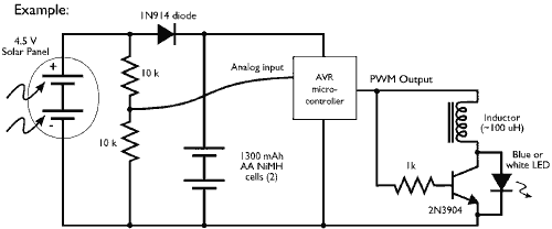
Microcontroller driving a Joule Thief circuit
This example demonstrates the PWM (pulse-width modulation) output of a microcontroller controlling a Joule Thief style voltage booster to power a white LED.
The circuit described utilizes a microcontroller to generate a PWM signal, which is an effective method for controlling...
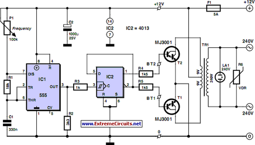
Cheap 12V to 220V Inverter
Although today's electrical appliances are increasingly self-powered, especially portable ones used for camping or summer holidays, there are still occasions when a 230 V AC source is necessary. If the power requirement from such a source remains relatively low—here, a...
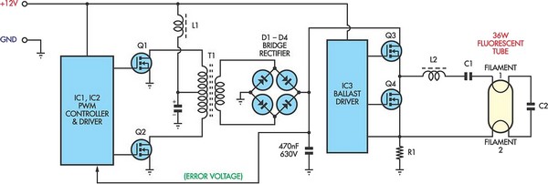
12V Flourescent Lamp Inverter
Fluorescent tubes consume significantly less energy compared to incandescent lamps and have a much longer lifespan. Additional benefits include diffuse, glare-free lighting and reduced heat output. Due to these advantages, fluorescent lighting is commonly preferred in commercial and retail spaces,...
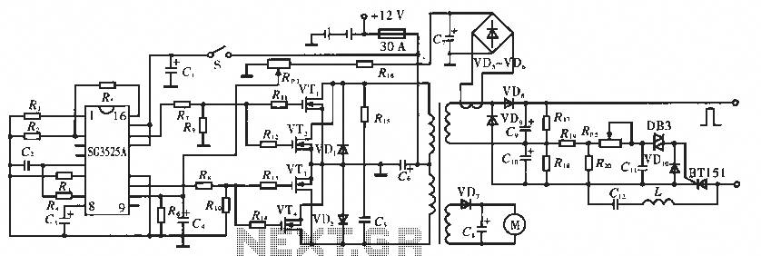
Electronic pulse circuitry fishing
The circuit utilizes the SC3525A, a PWM silicon chip from US General Semiconductor. It features an error amplifier with an inverting input at pin 1. Pin 2 serves as the non-inverting input for the error amplifier. Pins 5 and 6...
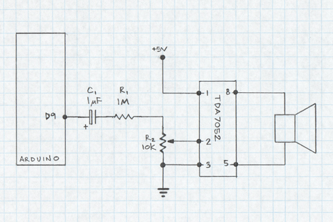
PWM sound Tutorial
This document demonstrates the use of an Arduino PWM output pin to generate sound. The output pin can be toggled rapidly between LOW and HIGH states to create a square wave. If the frequency of this square wave is within...
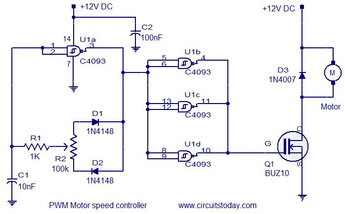
PWM motor speed controller
This circuit is designed based on a request from Mr. Vinoth in India. The requirement is for a 12V/5A DC fan motor controller. The circuit utilizes the quad 2-input Schmitt trigger IC CD4093 as its core component. Among the four...
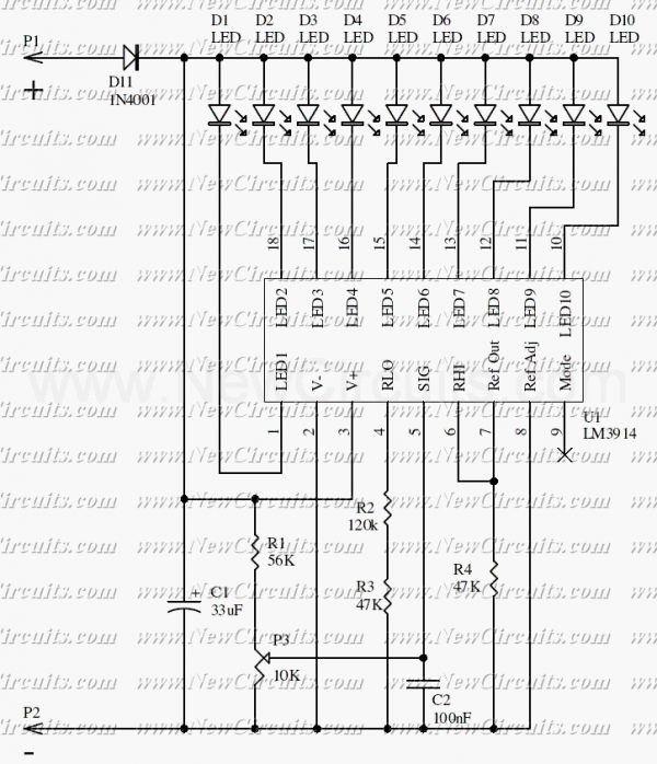
12V Led Car Battery Monitor
This simple circuit makes it possible to monitor the charging process to a higher level. Final adjustments are simple and the only thing needed is a digital voltmeter for the necessary accuracy. Connect an input voltage of 12.65 volts between...