


schematics Control speed of Nidec fan
#Nidec fan
#speed control
#12V fan
#cooling system
#cabinet ventilation
#PWM control
#electronics cooling
#thermal management
#DC fan
#fan controller
Description: A Nidec TA450DC B35502-35 fan has been installed in a large wooden cabinet housing a computer and other electronics, which generates significant heat. The fan is designed to draw air from the room and exhaust it through openings at the top of the cabinet. The fan features four wires: red (+12V), black (ground), blue, and yellow. Currently, only the red and black wires are used to power the fan at full speed, resulting in excessive noise. A toggle switch is used to turn the fan on and off. The objective is to replace the toggle switch with a variable speed control knob, allowing the fan speed to be adjusted. The minimum setting should provide just enough power for the fan to operate at its lowest speed, while the maximum setting should enable full speed operation. The user seeks guidance on the appropriate type of knob, wiring, and whether to utilize the additional blue and yellow wires for speed control, or to adjust the voltage instead.
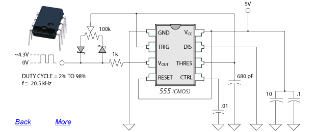
To achieve variable speed control for the Nidec TA450DC fan, a pulse-width modulation (PWM) controller can be employed. This method allows for effective speed regulation while maintaining low noise levels. The fan operates on a 12V DC supply, and the red wire is connected to the positive terminal, while the black wire connects to ground. The blue and yellow wires typically serve as a tachometer output and a PWM control input, respectively.
A suitable approach involves using a PWM speed controller circuit, which can be constructed using a transistor or a dedicated PWM controller IC. The PWM signal modulates the voltage supplied to the fan, effectively controlling its speed. The circuit can be designed with a potentiometer (variable resistor) that acts as the speed control knob. The potentiometer is connected in such a way that it adjusts the duty cycle of the PWM signal based on its position.
The wiring configuration would include connecting the potentiometer to the control input (yellow wire) of the fan. The PWM circuit's output will be fed into the yellow wire, while the blue wire can be left unconnected if it is solely for tachometer feedback, which may not be necessary for basic speed control.
For assembly, a small circuit board can be used to house the components. The PWM circuit will require a power source, which can be derived from the same 12V supply used to power the fan. The transistor or PWM controller IC can be mounted on the board, with the potentiometer accessible from the exterior for user adjustment.
In summary, the desired outcome is to create a simple yet effective PWM speed control circuit that utilizes a potentiometer to adjust the fan speed smoothly from minimum to maximum, while ensuring that the fan operates quietly and efficiently within the wooden cabinet.I have a Nidec TA450DC B35502-35 fan which I`ve installed in a large wooden cabinet where my computer and other electronics sit. This cabinet of course gets hot from all the electronics inside of it. The fan forces air in from the room and goes out through openings in the top of the cabinet. This fan has 4 wires: red (+12v), black (ground), and then blue and yellow. I`m using only red and black to give the fan full 12v power. The problem is since it`s at max speed, it is way too loud. I have a simple toggle switch to turn it on and off. What I would like to do is replace the toggle switch with a knob to adjust the speed. I don`t know how to use the other two wires to control the speed. What kind of knob do I need to get, and how should I wire it The minimum setting of the knob should feed the fan with its minimum required power to spin at the lowest speed possible, and the highest setting should spin it at full possible speed. I don`t have any problem with soldering a small circuit board together for this project, I just have no idea what schematic I need to put together.
I`ve played with electronics and their components all my life but don`t know nearly enough to even begin understanding how to accomplish this. It should be simple, right Should I be using one or both of the additional wires for this, or should I use some method of adjusting the voltage
To achieve variable speed control for the Nidec TA450DC fan, a pulse-width modulation (PWM) controller can be employed. This method allows for effective speed regulation while maintaining low noise levels. The fan operates on a 12V DC supply, and the red wire is connected to the positive terminal, while the black wire connects to ground. The blue and yellow wires typically serve as a tachometer output and a PWM control input, respectively.
A suitable approach involves using a PWM speed controller circuit, which can be constructed using a transistor or a dedicated PWM controller IC. The PWM signal modulates the voltage supplied to the fan, effectively controlling its speed. The circuit can be designed with a potentiometer (variable resistor) that acts as the speed control knob. The potentiometer is connected in such a way that it adjusts the duty cycle of the PWM signal based on its position.
The wiring configuration would include connecting the potentiometer to the control input (yellow wire) of the fan. The PWM circuit's output will be fed into the yellow wire, while the blue wire can be left unconnected if it is solely for tachometer feedback, which may not be necessary for basic speed control.
For assembly, a small circuit board can be used to house the components. The PWM circuit will require a power source, which can be derived from the same 12V supply used to power the fan. The transistor or PWM controller IC can be mounted on the board, with the potentiometer accessible from the exterior for user adjustment.
In summary, the desired outcome is to create a simple yet effective PWM speed control circuit that utilizes a potentiometer to adjust the fan speed smoothly from minimum to maximum, while ensuring that the fan operates quietly and efficiently within the wooden cabinet.I have a Nidec TA450DC B35502-35 fan which I`ve installed in a large wooden cabinet where my computer and other electronics sit. This cabinet of course gets hot from all the electronics inside of it. The fan forces air in from the room and goes out through openings in the top of the cabinet. This fan has 4 wires: red (+12v), black (ground), and then blue and yellow. I`m using only red and black to give the fan full 12v power. The problem is since it`s at max speed, it is way too loud. I have a simple toggle switch to turn it on and off. What I would like to do is replace the toggle switch with a knob to adjust the speed. I don`t know how to use the other two wires to control the speed. What kind of knob do I need to get, and how should I wire it The minimum setting of the knob should feed the fan with its minimum required power to spin at the lowest speed possible, and the highest setting should spin it at full possible speed. I don`t have any problem with soldering a small circuit board together for this project, I just have no idea what schematic I need to put together.
I`ve played with electronics and their components all my life but don`t know nearly enough to even begin understanding how to accomplish this. It should be simple, right Should I be using one or both of the additional wires for this, or should I use some method of adjusting the voltage
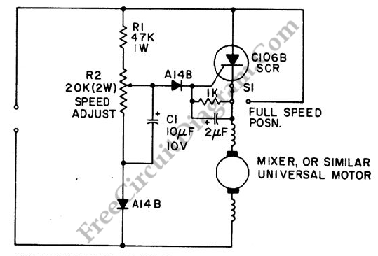
Mixer or Sewing Machine Motor Speed Control
A simple half-wave motor speed control circuit is effective for small universal AC/DC motors, with a maximum current capability of two amps RMS.
The half-wave motor speed control circuit utilizes a diode to allow current to flow in only one direction,...
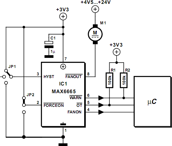
Fan Controller Using Just Two Components
The Maxim MAX 6665 provides a complete temperature-dependent fan controller. It can switch fans operating at voltages of up to 24 V and currents of up to 250 mA. The IC is available from the manufacturer in versions with preset...
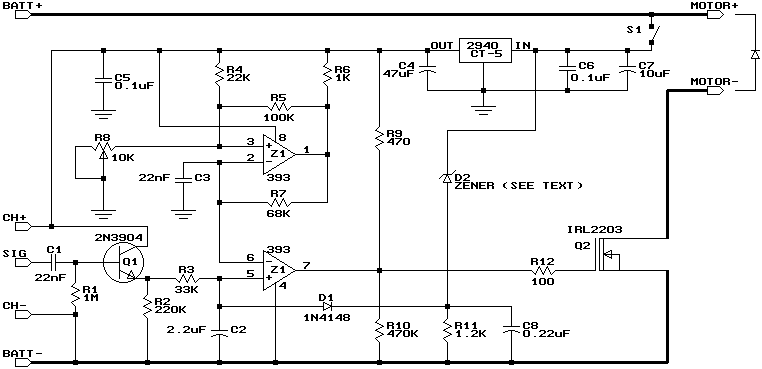
Build a Miniature High-Rate Speed Control with Battery Eliminator Circuit (BEC)
This design is based on a publication by Milan Lulic in the German magazine elektroModell. Lulic's design utilizes surface mount technology (SMT), while this version employs standard off-the-shelf components, making it more accessible for hobbyists. For those interested in a...
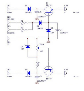
DC fan control circuit for power amplifier Schematic Diagram
DC fan control circuit for a power amplifier. It features a variable speed DC fan that operates based on the input signal. The speed of the fan's rotation is dependent on the amplitude of the input signal received from the...
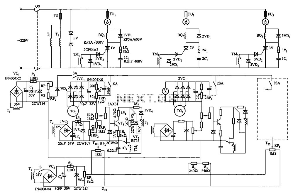
Multi-unit slip motor speed control system synchronous operation circuit
Collaboration with the dancers balanced bridge long on the porcelain unit. A sync adjustment rheostat speed control system is shown in Figure 3. The principle of speed control for electro-magnetic and photoelectric dancers is similar. The main motor (BQ2) allows...
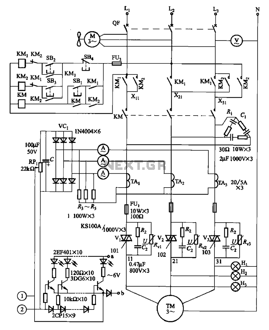
Two motor speed control circuit and the main level indicating circuit
The circuit illustrated in Figure 3-178 is designed for controlling the speed and torque of a motor used in a continuous casting machine. It consists of the main circuit, a trigger circuit, and both manual and automatic control signal circuits,...
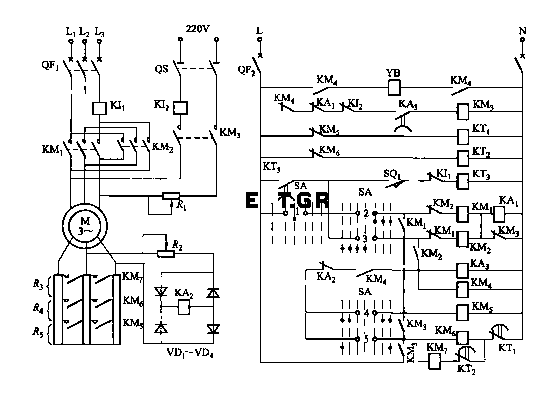
Forward and reverse speed control circuit can be integrated with a brake function
Figure 3173 illustrates a control circuit for a wound rotor induction motor that enables mechanical braking, dynamic braking, and reverse braking functions. The circuit includes various components such as relays, contactors, and time relays to manage the motor's speed in...
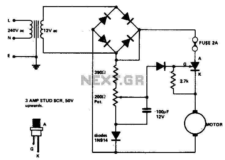
Speed control for model trains or cars
Low voltage speed control provides excellent starting torque and effective speed regulation. Additionally, a reversing switch can be integrated into the motor leads.
Low voltage speed control circuits are essential in applications where precise motor control is required, such as in...
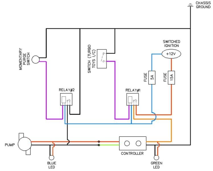
Coolingmist Installation
Coolingmist Stage 3 HOM Trunkmount kit installation is underway to enable continuous enjoyment of the HOM system. The setup includes a switch for arming the system and a separate push-button for purging. The intercooler sprayer assembly will be removed as...