


Self-excitation - one short brake circuit
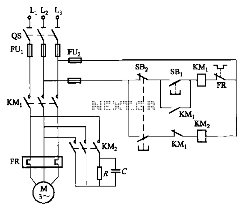
Description: The 3F155 circuit, as depicted in the provided figure, operates in manual control mode. It features a self-excitation braking phase, while the other two phases utilize a short brake. A resistor (R) is involved, along with the voltage across a capacitor (C) in the phase. The circuit also includes a three-phase current waveform that exhibits characteristics similar to self-excitation, but with a rapid attenuation effect.
The 3F155 circuit is designed to facilitate controlled braking in three-phase systems, particularly in applications requiring precise manual intervention. The manual control mode allows the operator to adjust the braking parameters in real-time, enhancing operational flexibility. The self-excitation braking phase is crucial as it enables the system to generate the necessary braking torque without relying on external power sources. This feature is particularly beneficial in scenarios where quick response times are essential.
In this circuit, the resistor (R) plays a pivotal role in regulating the voltage across the capacitor (C). This voltage is critical for maintaining the stability of the braking phase and ensuring that the current waveform remains within acceptable limits. The capacitor's charging and discharging cycles influence the overall performance of the circuit, allowing for effective energy management during braking operations.
The three-phase current waveform produced by the circuit closely resembles that of self-excitation, characterized by its rapid decay or attenuation. This rapid attenuation is advantageous in applications where swift cessation of motion is required, minimizing the risk of overshoot or excessive momentum. The circuit's design ensures that the braking effect is both efficient and effective, contributing to the safety and reliability of the overall system.
In summary, the 3F155 circuit exemplifies an innovative approach to manual control in braking applications, integrating self-excitation principles with robust voltage regulation and rapid response capabilities. This combination of features positions the circuit as a valuable component in various industrial and commercial applications requiring precise control over three-phase motor systems.3F155 circuit shown in FIG. It uses manual control mode. The figure, a self-excitation braking phase, the other two phases using short brake. Resistor R, the voltage across cap acitor C- phase, three-phase current waveform and similar self-excitation, but attenuates light fast.
The 3F155 circuit is designed to facilitate controlled braking in three-phase systems, particularly in applications requiring precise manual intervention. The manual control mode allows the operator to adjust the braking parameters in real-time, enhancing operational flexibility. The self-excitation braking phase is crucial as it enables the system to generate the necessary braking torque without relying on external power sources. This feature is particularly beneficial in scenarios where quick response times are essential.
In this circuit, the resistor (R) plays a pivotal role in regulating the voltage across the capacitor (C). This voltage is critical for maintaining the stability of the braking phase and ensuring that the current waveform remains within acceptable limits. The capacitor's charging and discharging cycles influence the overall performance of the circuit, allowing for effective energy management during braking operations.
The three-phase current waveform produced by the circuit closely resembles that of self-excitation, characterized by its rapid decay or attenuation. This rapid attenuation is advantageous in applications where swift cessation of motion is required, minimizing the risk of overshoot or excessive momentum. The circuit's design ensures that the braking effect is both efficient and effective, contributing to the safety and reliability of the overall system.
In summary, the 3F155 circuit exemplifies an innovative approach to manual control in braking applications, integrating self-excitation principles with robust voltage regulation and rapid response capabilities. This combination of features positions the circuit as a valuable component in various industrial and commercial applications requiring precise control over three-phase motor systems.3F155 circuit shown in FIG. It uses manual control mode. The figure, a self-excitation braking phase, the other two phases using short brake. Resistor R, the voltage across cap acitor C- phase, three-phase current waveform and similar self-excitation, but attenuates light fast.
Switching two-speed motor control circuit
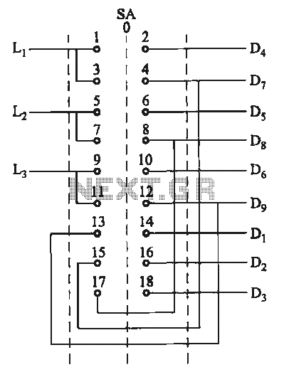
The motor switch control circuit depicted in the figure provides two speed settings for counter-steering, allowing for operation at two speeds in opposite directions.
The motor switch control circuit is designed to facilitate the operation of a motor at two distinct...
Tachometerless Motor Speed Control
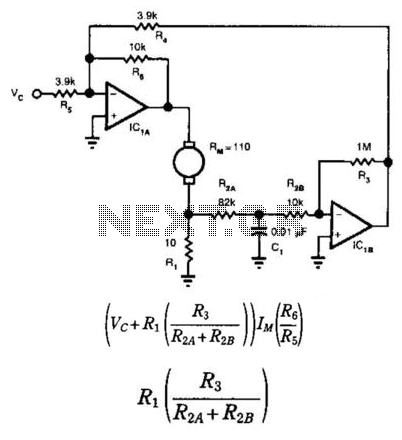
This circuit provides bidirectional speed regulation for small motors and does not require a tachometer. The voltage applied to the motor's windings, which is determined by summing amplifier IC1A, is expressed as a function of the command voltage (Vc) and...
Capacitor Box Circuit
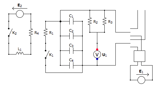
This is the discharging circuit. The red lines indicate the flow of energy from the capacitors to the terminals when the switch is in the upward position. The circuit is complete due to the connection of the terminals by Ni-Chrome...
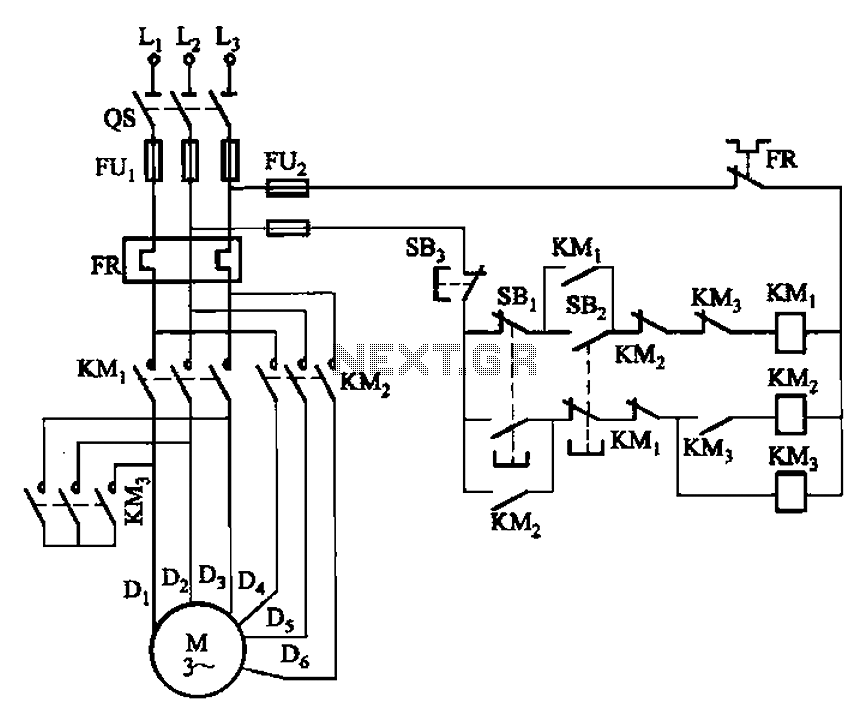
2Y- connection two-speed motor contactor control one circuit
The circuit depicted in Figure 3-96 features a low-speed operation button (SBz), a high-speed operation button (SBi), and a stop button (SB3). In this configuration, a motor is connected in such a way that when the low-speed button is pressed,...

Capacitor step-down DC power supply circuit
A capacitor step-down DC power supply circuit is presented. This circuit eliminates the need for power transformers, utilizing capacitive voltage drop rectification and regulation, which significantly reduces the overall size of the circuit. The circuit includes a capacitor step-down component,...
Switching two-speed motor control circuit
The motor switch control circuit depicted in the figure provides two speed settings for counter-steering, allowing for operation at two speeds in opposite directions.
The motor switch control circuit is designed to facilitate the operation of a motor at two distinct...
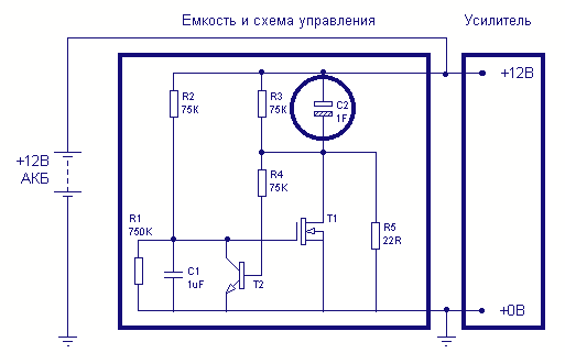
Car Large capacitor charge controllers
One-farad capacitors require some care. It's common knowledge that they must be pre-charged with a current-limiting resistor before plugging in. It is less common knowledge that those fifty-dollar smart cap controllers are in fact very simple devices, two dollars for...
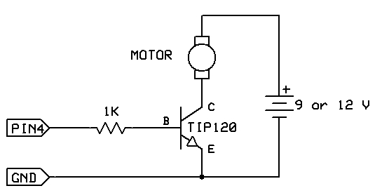
motor switch led circuit
The strategy involves assembling the circuit in stages, testing each component as it is integrated. Once all connections are established and can be controlled or read correctly by the computer, the main program can be developed with assurance that all...
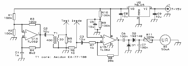
Capacitor internal resistor meter
The design presented here works by applying a 50kHz, 200mV square wave to the capacitor under test, in series with a 10 Ohm resistor. The AC voltage appearing across that resistor is measured and displayed on a meter. So the...