


SN754410 Dual Motor Control Circuit
#SN754410
#PIC
#LM7805
#dual motor
#motor driver
#microcontroller
#voltage regulator
#H-bridge
#DC motor
#control circuit
Description: The SN754410 Dual Motor Control circuit is illustrated below. It is straightforward in design, with the PIC serving as the central processor. The main components included in the schematic are the 7805 voltage regulator, the 18F452 microcontroller, and the SN754410 motor driver. The LM7805 provides a +5V regulated output, which is suitable for the PIC that operates on the +5V digital standard. Given that the motors have a low current demand, this regulated supply is also connected to the motor controller. The PIC 18F452 functions as the primary control unit, receiving analog inputs from PORTA pins 2 (RA0) and 3 (RA1). It evaluates these inputs and uses PORTD pins 19, 20, 21, and 22 to communicate with the motor controller, determining the direction and speed of the motors. The motor controller has four input pins labeled 1A, 2A, 3A, and 4A, with corresponding output pins for each half-H-bridge marked with a "Y" (e.g., 2Y). The digital supply powers both the signal and motor control, linking Vcc1 and Vcc2 to the +5V regulated power. Additionally, two Enable pins (pin 1 and pin 16) are connected to +5V through a 10kΩ resistor, ensuring that the H-bridges remain enabled. Alternatively, these pins could be connected to an I/O pin on the PIC for control, but this option has not been implemented in this design for simplicity.
The SN754410 Dual Motor Control circuit operates effectively for applications requiring precise motor control. The circuit design incorporates a robust structure that allows for the simultaneous control of two DC motors or one stepper motor through the use of H-bridge configurations. The LM7805 voltage regulator ensures that the microcontroller and motor driver receive a stable +5V supply, which is crucial for reliable operation.
In this circuit, the PIC 18F452 microcontroller plays a vital role, as it processes analog signals from the sensors or user inputs and translates them into digital signals that control the motor operations. The use of PORTA pins for analog inputs allows for the integration of various sensors, enabling the system to respond to external conditions. The output pins on PORTD are strategically assigned to control the motor driver, facilitating precise control over motor speed and direction.
The SN754410 motor driver is designed to handle the necessary current for the motors while providing features such as braking and direction control. The enable pins ensure that the H-bridges are always active, but they can also be modified for dynamic control through the microcontroller if desired. This flexibility allows for advanced control strategies, such as PWM (Pulse Width Modulation) for speed regulation.
Overall, this circuit exemplifies a practical approach to motor control, combining simplicity with functionality. It is suitable for various robotics and automation projects where precise motor control is essential.The SN754410 Dual Motor Control circuit can be seen below. It is just about as simple as it looks with the PIC being the central processor. The main parts used and seen in the schematic below are the 7805, 18F452 and SN754410. The LM7805 +5v Regulator is used for its simplicity and the fact that the PIC uses the +5v digital standard. Since our motors are not too current demanding, this regulated supply will also be connected to the motor controller. The PIC 18F452 acts as the primary input and output control unit. It will be taking the analog input from PORTA pins 2 (RA0) and 3 (RA1), evaulating this input and then using PORTD, pins 19, 20, 21 and 22 to tell the motor controller what motors to move where and how fast.
The Motor Controller has 4 input pins 1A, 2A, 3A and 4A. The corresponding output pin for each half-h-bridge is marked with a Y (i. e. 2Y). The digital supply will be used for both signal and motor control so Vcc1 and Vcc2 are tied to the +5v regulated power. Finally, two Enable pins (pin 1 and pin 16) are connected to +5v through a 10k © resistor so these h-bridges are always enabled.
You could alternatively connect this to an I/O pin on the PIC to control these enable bits, but for simplicity I have not done that here.
The SN754410 Dual Motor Control circuit operates effectively for applications requiring precise motor control. The circuit design incorporates a robust structure that allows for the simultaneous control of two DC motors or one stepper motor through the use of H-bridge configurations. The LM7805 voltage regulator ensures that the microcontroller and motor driver receive a stable +5V supply, which is crucial for reliable operation.
In this circuit, the PIC 18F452 microcontroller plays a vital role, as it processes analog signals from the sensors or user inputs and translates them into digital signals that control the motor operations. The use of PORTA pins for analog inputs allows for the integration of various sensors, enabling the system to respond to external conditions. The output pins on PORTD are strategically assigned to control the motor driver, facilitating precise control over motor speed and direction.
The SN754410 motor driver is designed to handle the necessary current for the motors while providing features such as braking and direction control. The enable pins ensure that the H-bridges are always active, but they can also be modified for dynamic control through the microcontroller if desired. This flexibility allows for advanced control strategies, such as PWM (Pulse Width Modulation) for speed regulation.
Overall, this circuit exemplifies a practical approach to motor control, combining simplicity with functionality. It is suitable for various robotics and automation projects where precise motor control is essential.The SN754410 Dual Motor Control circuit can be seen below. It is just about as simple as it looks with the PIC being the central processor. The main parts used and seen in the schematic below are the 7805, 18F452 and SN754410. The LM7805 +5v Regulator is used for its simplicity and the fact that the PIC uses the +5v digital standard. Since our motors are not too current demanding, this regulated supply will also be connected to the motor controller. The PIC 18F452 acts as the primary input and output control unit. It will be taking the analog input from PORTA pins 2 (RA0) and 3 (RA1), evaulating this input and then using PORTD, pins 19, 20, 21 and 22 to tell the motor controller what motors to move where and how fast.
The Motor Controller has 4 input pins 1A, 2A, 3A and 4A. The corresponding output pin for each half-h-bridge is marked with a Y (i. e. 2Y). The digital supply will be used for both signal and motor control so Vcc1 and Vcc2 are tied to the +5v regulated power. Finally, two Enable pins (pin 1 and pin 16) are connected to +5v through a 10k © resistor so these h-bridges are always enabled.
You could alternatively connect this to an I/O pin on the PIC to control these enable bits, but for simplicity I have not done that here.
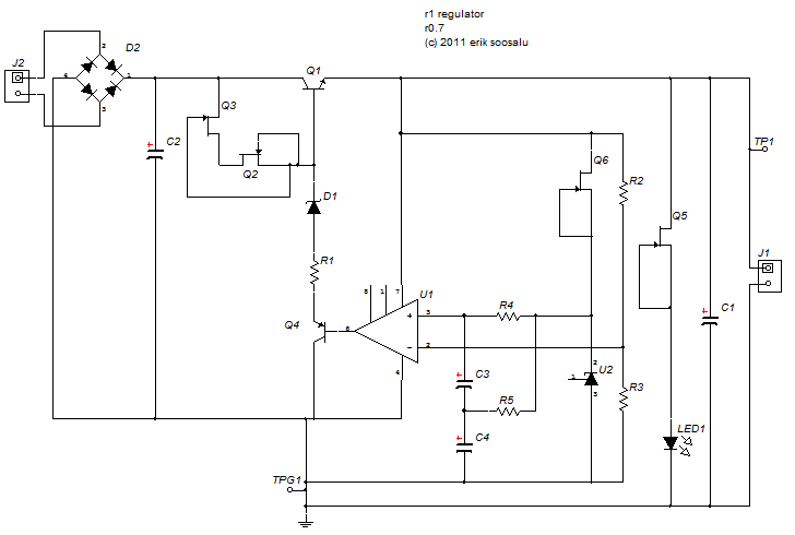
A TREAD sized regulator
The size of the tread was 5 cm by 3 cm. The current design measures 5 cm by 3.3 cm. The regulator's foundation is based on Walt Jung's 1997 article, "Regulator Excels in Noise and Line Rejection," with modifications derived...
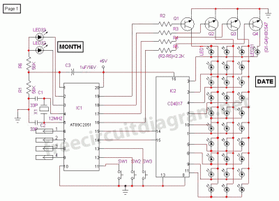
Digital Calender Circuit
This is a digital calendar circuit that utilizes a microcontroller to display the date, day, and month on an LED display. The entire system is managed by an 8-bit microcontroller, which operates based on a program embedded in its ROM....
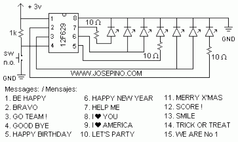
ON/OFF button using Microcontrollers
Using a switch to power up your microcontroller projects may not be a good idea if you need to "wake" the PIC during some events. For example: A metal detector sends a pulse indicating a car is ready to enter...
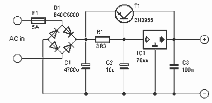
5 A stabilized power supply
This is a simple but powerful nutrition that less than 5 A can deliver. The circuit works by using a normal type 78xx voltage regulator and a buffer transistor. When the output current over 200 mA, then take over the...
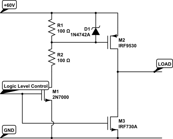
current simple h-bridge polarity reversal
Construct an H-bridge specifically for reversing current, as speed control is managed separately. Is it feasible to connect two N-channel MOSFETs and two P-channel MOSFETs to an IO pin from the microcontroller (with appropriate resistors), or is the process more...
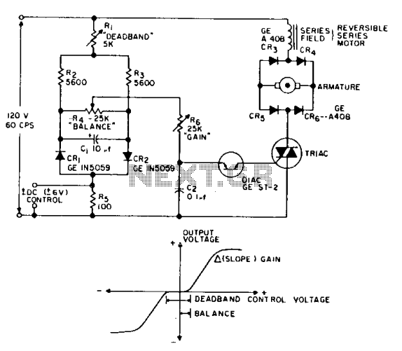
Reversing motor drive dc control
This is a positioning servo drive that includes adjustments for balance, gain, and deadband. In addition to receiving control from a DC signal, a mechanical input can be utilized for the balance control. Alternatively, this balance control can be substituted...
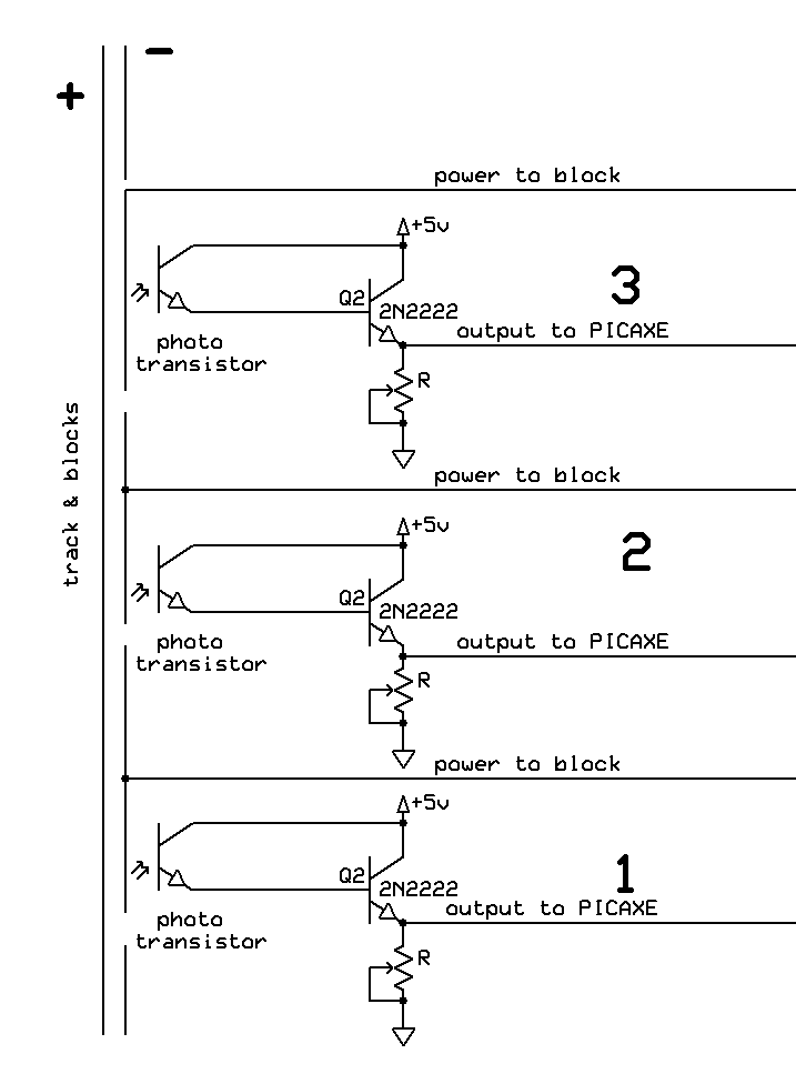
Automatic Switch Project 2
The switch control system utilizes sensors to inform the microcontroller of the trains' positions on the layout. This ensures that only one train occupies the main line at any given time and that switches are correctly set for the train's...
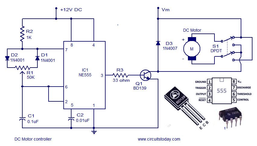
Dc motor speed controller circuit using NE555
A DC motor controller based on an NE555 timer is presented here. The direction of rotation of the DC motor can also be changed using this DC motor speed control circuit.
The described circuit utilizes the NE555 timer IC in astable...
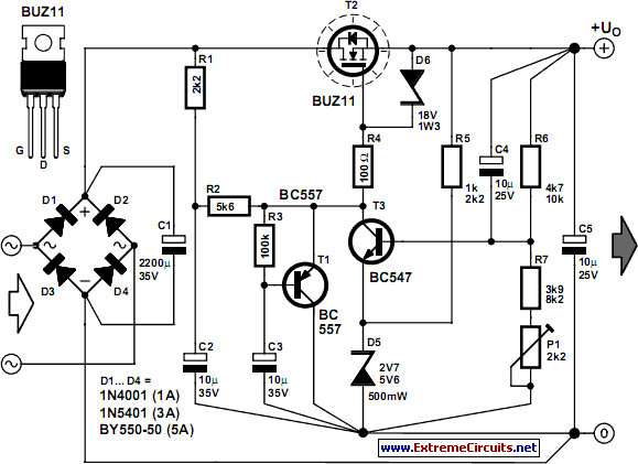
Stable Filament Power Supply Circuit
The circuit diagram illustrates a voltage regulator designed from discrete components to meet specific voltage requirements. It provides two sets of component values for output voltages of 6.3 V (upper) and 12.6 V (lower). The components used include BC547 and...