


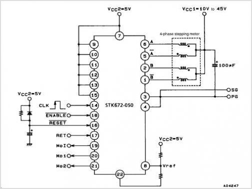
STK672-050 Microstep Operation-supported 4-phase Stepping Motor Driver (io= 3.0a) Semicon Device
#stepping motor
#microstep operation
#motor driver
#STM1061
#voltage detector
#battery monitoring
#power supply
#voltage threshold
#precision comparator
#low power
Description: The STM1061 low power voltage detector monitors battery, power supply, and regulated system voltages. A precision voltage reference and comparator assess the V_CC input, comparing it with a specified voltage threshold. When V_CC falls below the defined trip point threshold, the output (OUT) is driven low and remains asserted as long as the V_CC input is below the V_TH + hysteresis (V_HYST). The STM1061 is guaranteed to output the correct logic state for V_CC down to 0.7V and is designed to ignore fast transients on V_CC. This device is manufactured by STMicroelectronics.
The STM1061 voltage detector is an integrated circuit designed for low-power applications, providing reliable monitoring of supply voltages in battery-operated and low-voltage systems. It features a precision voltage reference that ensures accurate voltage detection, which is critical for maintaining system stability and preventing undervoltage conditions.
The comparator within the STM1061 continuously monitors the V_CC input. When the voltage drops below a predetermined threshold (V_TH), the output pin (OUT) transitions to a low state, indicating that the monitored voltage is no longer within the acceptable range. This output remains low until the voltage rises above the threshold plus a defined hysteresis (V_HYST), preventing rapid toggling of the output state due to minor fluctuations in the input voltage.
This hysteresis feature is particularly important in noisy environments or applications where voltage levels may fluctuate rapidly. By defining a clear threshold for output state changes, the STM1061 enhances the reliability of the voltage detection process. The device is also capable of operating correctly at input voltages as low as 0.7V, making it suitable for low-voltage applications.
The STM1061's design includes provisions to ignore fast transients on the V_CC input, ensuring that temporary spikes or dips in voltage do not inadvertently trigger the output. This characteristic allows for stable operation in dynamic environments where voltage levels may be subject to rapid changes.
Overall, the STM1061 low power voltage detector is an essential component for ensuring the integrity of power supply systems, providing a robust solution for voltage monitoring in various electronic applications.The STM1061 low power voltage detector provides monitoring of battery, power-supply, and regulated system voltages. A precision Voltage Reference and Comparator monitors the V CC input and compares it with a specified voltage threshold condition.
When V falls below a CC specified trip point threshold, the output (OUT) is forced low and remains ass erted as long as the V input remains below V + hysteresis (V ). The STM1061 device is CC TH, HYST guaranteed to output the correct Logic state for V down to 0. 7V. They are also designed to CC ignore fast transients on V. CC By STMicroelectronics
The STM1061 voltage detector is an integrated circuit designed for low-power applications, providing reliable monitoring of supply voltages in battery-operated and low-voltage systems. It features a precision voltage reference that ensures accurate voltage detection, which is critical for maintaining system stability and preventing undervoltage conditions.
The comparator within the STM1061 continuously monitors the V_CC input. When the voltage drops below a predetermined threshold (V_TH), the output pin (OUT) transitions to a low state, indicating that the monitored voltage is no longer within the acceptable range. This output remains low until the voltage rises above the threshold plus a defined hysteresis (V_HYST), preventing rapid toggling of the output state due to minor fluctuations in the input voltage.
This hysteresis feature is particularly important in noisy environments or applications where voltage levels may fluctuate rapidly. By defining a clear threshold for output state changes, the STM1061 enhances the reliability of the voltage detection process. The device is also capable of operating correctly at input voltages as low as 0.7V, making it suitable for low-voltage applications.
The STM1061's design includes provisions to ignore fast transients on the V_CC input, ensuring that temporary spikes or dips in voltage do not inadvertently trigger the output. This characteristic allows for stable operation in dynamic environments where voltage levels may be subject to rapid changes.
Overall, the STM1061 low power voltage detector is an essential component for ensuring the integrity of power supply systems, providing a robust solution for voltage monitoring in various electronic applications.The STM1061 low power voltage detector provides monitoring of battery, power-supply, and regulated system voltages. A precision Voltage Reference and Comparator monitors the V CC input and compares it with a specified voltage threshold condition.
When V falls below a CC specified trip point threshold, the output (OUT) is forced low and remains ass erted as long as the V input remains below V + hysteresis (V ). The STM1061 device is CC TH, HYST guaranteed to output the correct Logic state for V down to 0. 7V. They are also designed to CC ignore fast transients on V. CC By STMicroelectronics
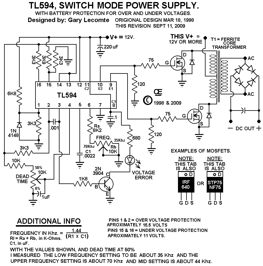
A 12 Volt Switching Power Supply
This circuit is designed for individuals needing to boost or drop a voltage. The output operates at high frequency but can be rectified and filtered to provide a DC output. When rectifying high frequencies, it is essential to utilize high-speed...
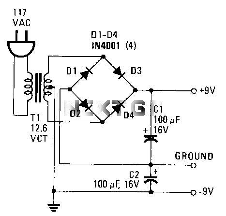
Simple-power-supply
This power supply provides both +9 V and -9 V outputs to replace two 9-V batteries. The rectifier circuit consists of two separate full-wave rectifiers, each connected to the secondary winding of the transformer. The first full-wave rectifier, made up...
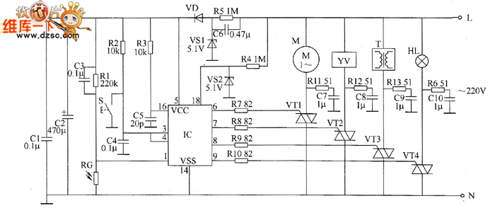
Industrial fuel oil furnace controller circuit diagram 2
The industrial fuel oil furnace controller circuit consists of a power supply circuit, a testing and ignition control circuit, and a control implementation circuit, as illustrated in the accompanying diagram. The power supply circuit includes a step-down capacitor (C6), a...
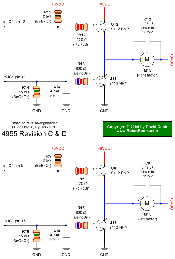
Big Trak Motor Driver Schematic
Schematic of Big Trak's motor driver circuit. The toy includes 9112 and 9113 transistors (and sometimes 2N6715) because the 75494 chip cannot supply enough current to run the Big Trak's motors by itself.
The motor driver circuit for the Big Trak...
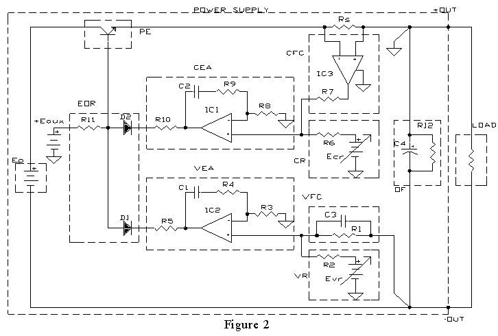
AMPLIFIER WITH FORCED EQUILIBRIUM ADAPTOR
Each power supply, whether linear or switching, operates in at least two modes: constant voltage (CV) and constant current (CC). The power supply can function in either mode, with the other serving as a protective mode for both the load...
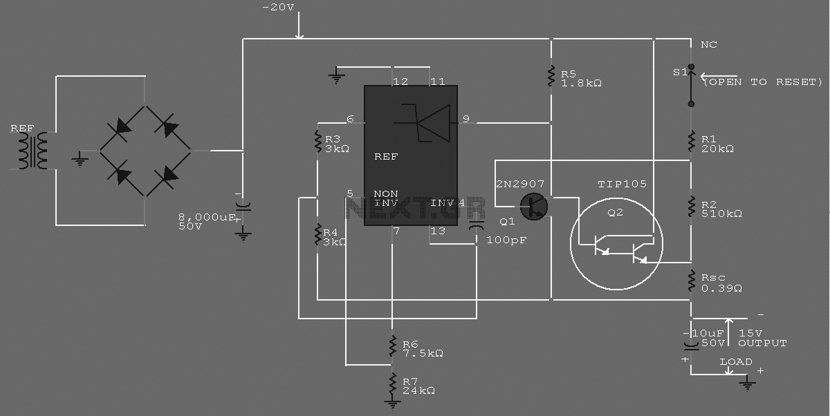
-15 V 1-A Regulated Power Supply
The supply receives -20 V from the rectifier/filter which is fed to the collector of the Darlington pnp pass transistor, a TIP105. The base drive to the TIP105 is supplied through resistor R5. The base of the TIP is driven...
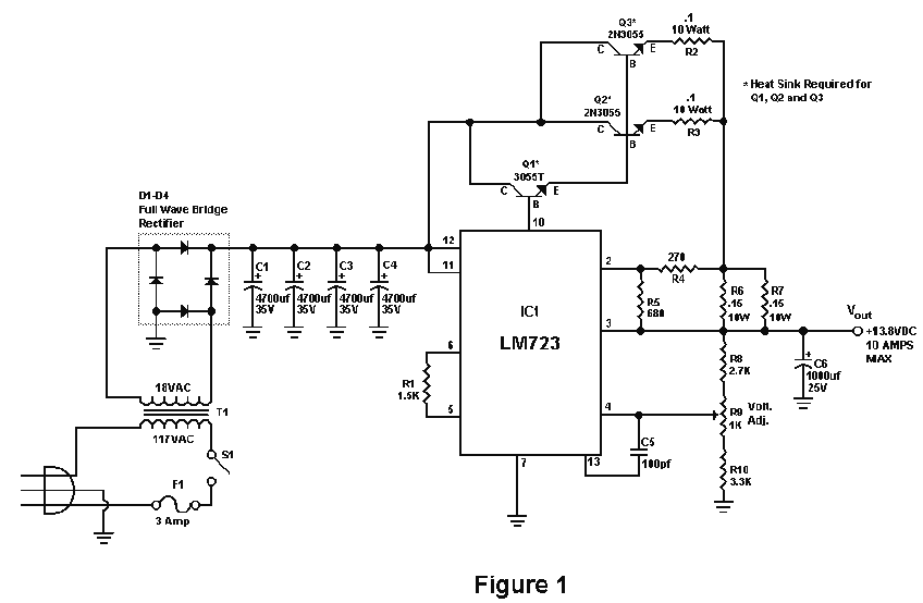
10 Amp 13.8 Volt Power Supply
Sometimes amateurs like to home-brew their power supplies instead of purchasing one off the shelf at any of the major ham radio retail dealers. The advantage to rolling your own power supply is that it teaches us how they work...
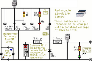
Circuit Diagram Of Alarm Power Supply
The following circuit illustrates an Alarm Power Supply Circuit Diagram. Features include a 1-amp current output, suitable for a Modular Burglar Alarm operating at 12 volts.
The Alarm Power Supply Circuit is designed to provide a stable and reliable power source...
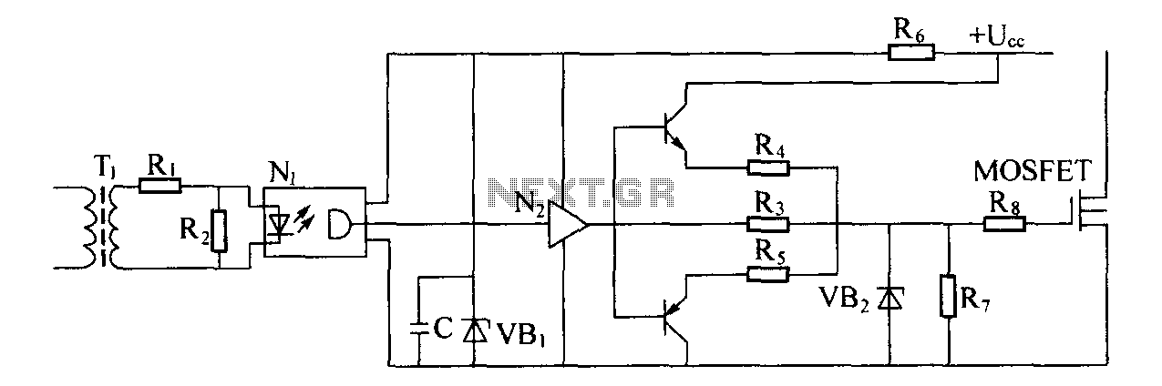
Switching power supply drive circuit
Driver circuit diagram: The primary function of the driver circuit is to serve as a variable width pulse width modulator output power amplifier, providing a drive signal to high voltage power switching devices. The driving circuit typically plays a role...