


TDA7275A DC motor speed controller circuit
#TDA7275A
#DC motor
#speed controller
#linear integrated circuit
#speed regulator
#record players
#tape recorders
#cassette recorders
#small motors
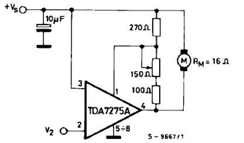
Description: The TDA7275A linear integrated circuit, housed in a minidip plastic package, can be utilized to design a straightforward speed regulator electronic project suitable for regulating the speed of small DC motors. The TDA7275A DC speed controller project is specifically intended for use as a speed regulator for DC motors found in record players, tape players, and cassette recorders. This DC motor speed controller circuit can deliver a maximum output current of 1.5 amperes and operates within a voltage range of 8 to 18 volts. The voltage for Motor "Run" is typically set at 1.5 volts (as per the provided data or when open), while for Motor "Stop," it is 1 volt (as per the provided data or when grounded).
The TDA7275A circuit is designed to provide efficient control over the speed of small DC motors, making it ideal for applications in consumer electronics such as audio equipment. The integrated circuit offers a simple yet effective method to adjust motor speed by varying the voltage supplied to the motor based on the desired operational state.
In practical applications, the circuit can be configured with additional components such as resistors, capacitors, and diodes to enhance performance and ensure stability under varying load conditions. The maximum output current of 1.5 amperes allows it to drive small motors effectively, while the specified voltage range of 8 to 18 volts provides flexibility in power supply options.
For implementation, the circuit can be connected to a simple control interface, which allows the user to switch between the "Run" and "Stop" states. The use of a potentiometer can further facilitate fine-tuning of the motor speed, providing a more precise control mechanism.
Overall, the TDA7275A linear integrated circuit serves as a reliable foundation for developing a straightforward and efficient DC motor speed regulation solution, suitable for a variety of small motor applications in the electronics field.Using the TDA7275A linear integrated circuit manufactured in a minidip plastic package can be designed a very simple speed regulator electronic project that can be used for speed regulation of small DC motors . TDA7275A DC speed controller project is intended for use as speed regulator for DC motors of record players, tape and cassette recorders.
This DC motor speed controller circuit project can provide a maximum output current of 1.5 amperes . This circuit can be powered with a voltage range between 8 and 18 volts . V2 is typically 1.5 volt for Motor ”Run” (Acc. Following data or open) and 1 volt for Motor ”Stop” (Acc. Following data or grounded) .
The TDA7275A circuit is designed to provide efficient control over the speed of small DC motors, making it ideal for applications in consumer electronics such as audio equipment. The integrated circuit offers a simple yet effective method to adjust motor speed by varying the voltage supplied to the motor based on the desired operational state.
In practical applications, the circuit can be configured with additional components such as resistors, capacitors, and diodes to enhance performance and ensure stability under varying load conditions. The maximum output current of 1.5 amperes allows it to drive small motors effectively, while the specified voltage range of 8 to 18 volts provides flexibility in power supply options.
For implementation, the circuit can be connected to a simple control interface, which allows the user to switch between the "Run" and "Stop" states. The use of a potentiometer can further facilitate fine-tuning of the motor speed, providing a more precise control mechanism.
Overall, the TDA7275A linear integrated circuit serves as a reliable foundation for developing a straightforward and efficient DC motor speed regulation solution, suitable for a variety of small motor applications in the electronics field.Using the TDA7275A linear integrated circuit manufactured in a minidip plastic package can be designed a very simple speed regulator electronic project that can be used for speed regulation of small DC motors . TDA7275A DC speed controller project is intended for use as speed regulator for DC motors of record players, tape and cassette recorders.
This DC motor speed controller circuit project can provide a maximum output current of 1.5 amperes . This circuit can be powered with a voltage range between 8 and 18 volts . V2 is typically 1.5 volt for Motor ”Run” (Acc. Following data or open) and 1 volt for Motor ”Stop” (Acc. Following data or grounded) .
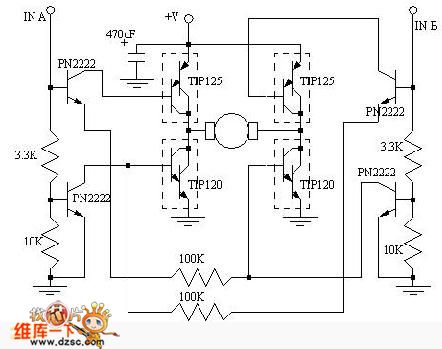
DC Motor Control
Regarding the DC motor control problem, this circuit is intended to assist individuals with specific requirements. The circuit's functions for co-rotation, rollback, deceleration, and stopping can be managed by the connected microcontroller unit (MCU).
The DC motor control circuit is designed...
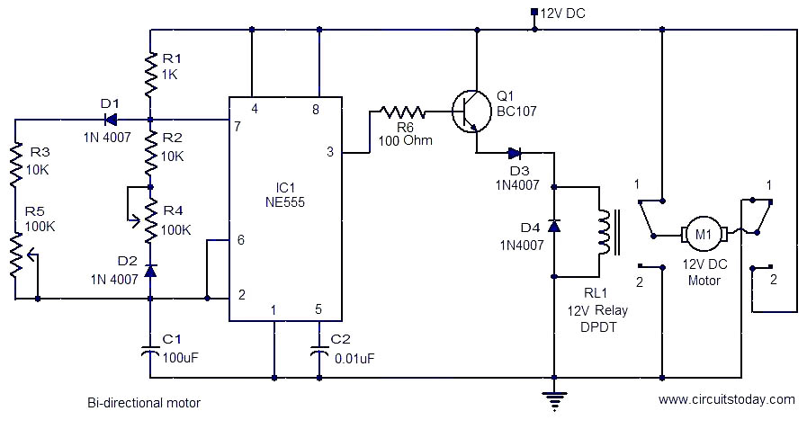
Bi-directional motor
This is a simple and easy-to-construct circuit designed to provide a bidirectional drive for a DC motor. The circuit operates straightforwardly. The output of an astable multivibrator based on IC1 (NE555) is utilized to control the relay RL1 that drives...
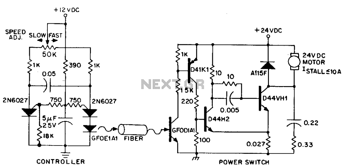
DC variable speed motor control
DC power can also be controlled using fiber optics. The circuit provides an insulated speed control path for a small DC actuator motor (less than Vn hp). The control logic is a self-contained module that requires approximately 300 mW at...
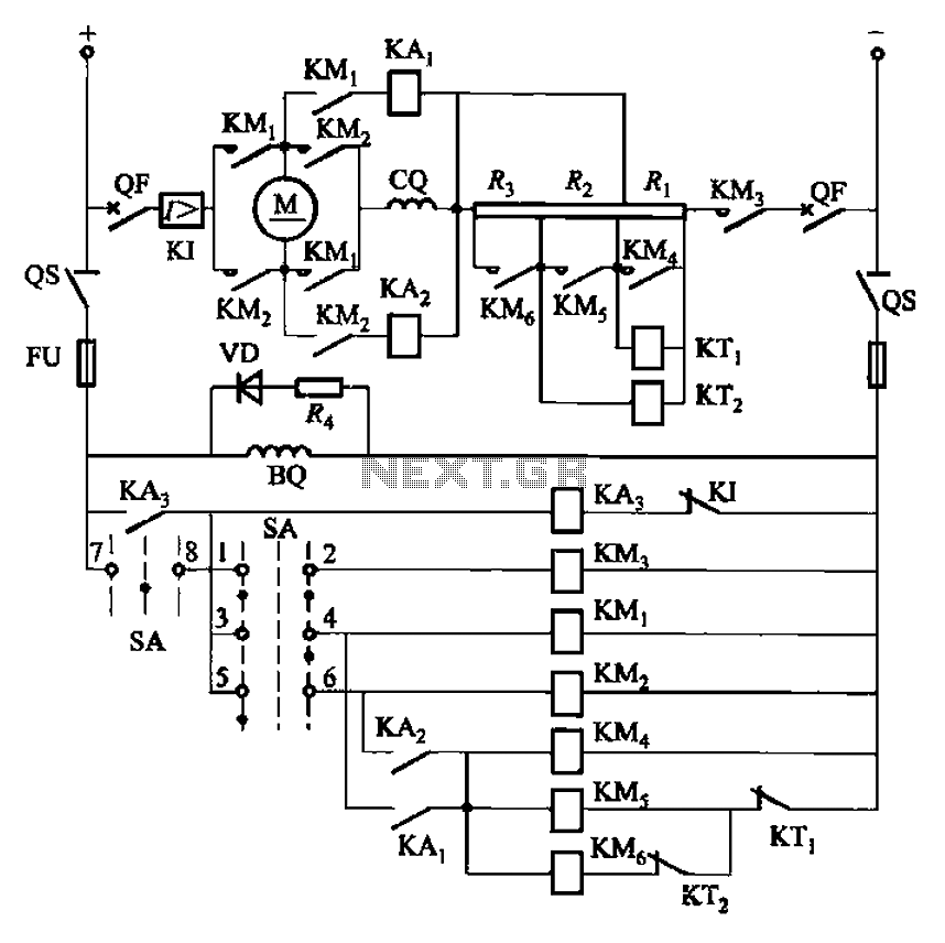
One of reversing circuit reverse braking resistor in series with a DC motor armature start
The circuit depicted in Figure 3-201 includes two starting resistors, with one controlled by a time relay. A master switch (SA) is utilized to manage the motor's reversing operation. The circuit incorporates a reverse braking mechanism, which is automatically controlled...
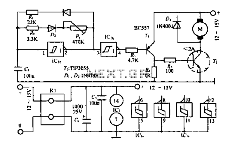
A small DC motor control circuit a
The core multi-resonant circuit 40 L06 has a collapse time of 1C. An auxiliary electric signal operates below its low threshold, opening Icl. The output is provided through two terminals for business use. The circuit includes components such as CI,...
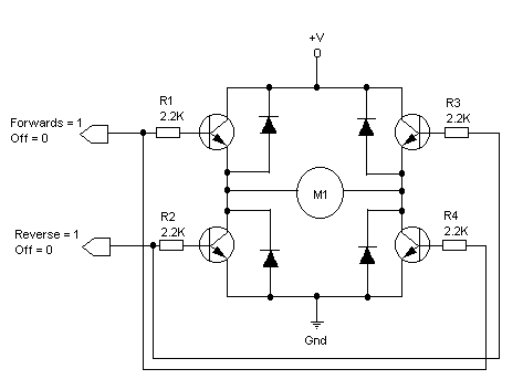
Controlling DC Motors Robotics Tutorial
The principles of DC motors are discussed in the beginner and intermediate sections of this tutorial. This section will address the electronics required to interface them with a Basic X microcontroller or other digital chips. The simplest method of controlling...
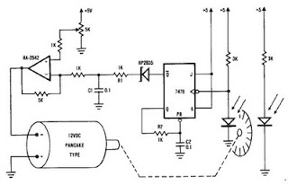
dc motor 12v speed controller circuit
A simple encoder circuit for a DC motor can be constructed using the provided circuit diagram. The system includes the HA-2542 operational amplifier, a small 12 V DC motor, and a position encoder. During operation, the encoder generates a series...
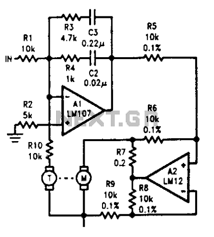
Motor-tachometer speed control
The tachometer, mounted on the same shaft as the DC motor, functions as a generator, producing a DC output voltage that is proportional to the motor's speed. A summing amplifier, labeled as Al, manages its output to ensure that the...
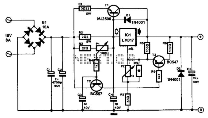
Mini-Drill Control
This circuit is designed for speed control of small DC motors commonly found in devices such as electric drills, which are utilized for precision engineering and drilling tasks. The behavior of these motors, typically permanent magnet types, resembles that of...