


The beginning and end of a three-phase motor winding speed judgment circuit
#three-phase motor
#winding speed
#double throw switch
#motor control
#phase switching
#speed judgment
#electrical circuits
#industrial motors
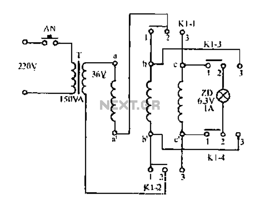
Description: Figure aa, bb, and ce represent three-phase windings. A double throw switch Kl-1 to Kl-4 is positioned on the left side, connecting phases 1 and 2. At this point, aa and bb are in series with the secondary of transformer T, a 6V 3W small bulb ZD is connected to the ends of ce. If windings a and b are connected to either the head or tail of aa and bb, pressing button A will induce a current, causing bulb ZD to illuminate through winding ce. Conversely, if a and b are not connected to the same terminal, the magnetic fields generated by aa and bb will offset each other, resulting in no induced current in ce, and bulb ZD will not light up. This process allows for identifying the same terminals of aa and bb. When the switch Kl-1 to Kl-4 is toggled to the other side, connecting phases 3 and 2, as depicted in the figure, bb and ce will interchange. In this scenario, pressing button N will similarly allow for identifying the corresponding terminals of aa and ce. Therefore, toggling switch Kl-1 to Kl-4 once is sufficient to distinguish the head and tail of the three-phase windings. In practical applications, it is recommended to first utilize a multimeter to identify the heads of the two windings, after which any of the windings can be connected to aa, bb, and ce interchangeably.
The circuit described involves a method to determine the orientation of three-phase windings (aa, bb, ce) using a double throw switch (Kl-1 to Kl-4) and an indicator bulb (ZD). The transformer (T) serves as a power source, providing the necessary voltage to illuminate the bulb, which acts as a visual indicator of the correct phase connections.
In the first configuration, when Kl-1 and Kl-2 are engaged, the windings aa and bb are connected in series with the transformer’s secondary output. The bulb ZD illuminates when the windings a and b are connected to the same terminal (either head or tail) of the respective windings. This is due to the induced current generated in winding ce, which is effectively linked to the output of the transformer through the series connection of aa and bb.
When the switch is toggled to connect phases 2 and 3, the roles of bb and ce are reversed, and pressing button N allows for a similar verification process for the terminals of aa and ce. This design allows for easy identification of the windings' polarity, which is crucial for ensuring proper operation in three-phase systems.
The circuit can be further enhanced by incorporating additional safety features, such as fuses or circuit breakers, to protect against overload conditions. Additionally, the use of a multimeter for initial testing is a prudent step to ensure that the windings are correctly identified before making any connections, thus preventing potential damage to the components.
Overall, this circuit serves as an effective means of determining the correct connections of three-phase windings, facilitating proper setup and operation in various electrical applications.FIG aa, bb, and ce three-phase windings, respectively. Double throw switch Kl-l ~ Kl-4 hit the left side, that switch l and 2 phase, at this time, aa and bb in series with the secondary of the transformer T, 6 3V small bulb ZD and connected to ce ends. If a and b are all connected winding aa and bb head or tail, then when the button is pressed A t, induced current, ZD luminous winding ce in. Conversely, if a and b are not the end of the same name, then aa and bb magnetic field generated by the mutual offset, ce no induced current, ZD does not shine.
Accordingly, we find out aa and bb end of the same name. When KH-Kl-4 and hit the other side, that the switch 3 and 2 phase, the figure shows, this time bb and ce just swap each other. In this case, if press N, the same way you can draw aa and ce the dot end. Thus, as long as the Kl-l ~ Kl-4 down once, then uh distinguish the head and tail of three-phase windings.
Real intertemporal use, first with a multimeter to find out which of the two windings are heads, then any of the windings connected to aa, bb and inter-cc can be.
The circuit described involves a method to determine the orientation of three-phase windings (aa, bb, ce) using a double throw switch (Kl-1 to Kl-4) and an indicator bulb (ZD). The transformer (T) serves as a power source, providing the necessary voltage to illuminate the bulb, which acts as a visual indicator of the correct phase connections.
In the first configuration, when Kl-1 and Kl-2 are engaged, the windings aa and bb are connected in series with the transformer’s secondary output. The bulb ZD illuminates when the windings a and b are connected to the same terminal (either head or tail) of the respective windings. This is due to the induced current generated in winding ce, which is effectively linked to the output of the transformer through the series connection of aa and bb.
When the switch is toggled to connect phases 2 and 3, the roles of bb and ce are reversed, and pressing button N allows for a similar verification process for the terminals of aa and ce. This design allows for easy identification of the windings' polarity, which is crucial for ensuring proper operation in three-phase systems.
The circuit can be further enhanced by incorporating additional safety features, such as fuses or circuit breakers, to protect against overload conditions. Additionally, the use of a multimeter for initial testing is a prudent step to ensure that the windings are correctly identified before making any connections, thus preventing potential damage to the components.
Overall, this circuit serves as an effective means of determining the correct connections of three-phase windings, facilitating proper setup and operation in various electrical applications.FIG aa, bb, and ce three-phase windings, respectively. Double throw switch Kl-l ~ Kl-4 hit the left side, that switch l and 2 phase, at this time, aa and bb in series with the secondary of the transformer T, 6 3V small bulb ZD and connected to ce ends. If a and b are all connected winding aa and bb head or tail, then when the button is pressed A t, induced current, ZD luminous winding ce in. Conversely, if a and b are not the end of the same name, then aa and bb magnetic field generated by the mutual offset, ce no induced current, ZD does not shine.
Accordingly, we find out aa and bb end of the same name. When KH-Kl-4 and hit the other side, that the switch 3 and 2 phase, the figure shows, this time bb and ce just swap each other. In this case, if press N, the same way you can draw aa and ce the dot end. Thus, as long as the Kl-l ~ Kl-4 down once, then uh distinguish the head and tail of three-phase windings.
Real intertemporal use, first with a multimeter to find out which of the two windings are heads, then any of the windings connected to aa, bb and inter-cc can be.
My Motors got me to Tap into Radiant Energy
A new user is seeking to share information about their experiences on this platform.
The user expresses a desire to communicate and engage with the community regarding their experiences. This indicates an interest in exchanging knowledge and possibly seeking assistance or...
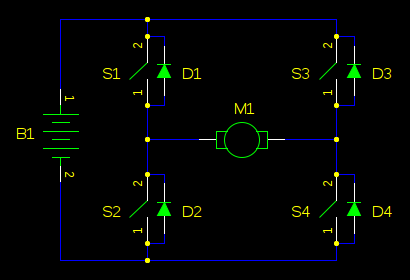
boost Why should I worry about a motor causing my supply voltage to shoot up when the back-EMF cant exceed the supply voltage
In motor control circuits, precautions must be taken to prevent the motor from feeding back into the power supply, which can cause the supply voltage to rise and potentially damage components. However, unless an external force is accelerating the motor,...
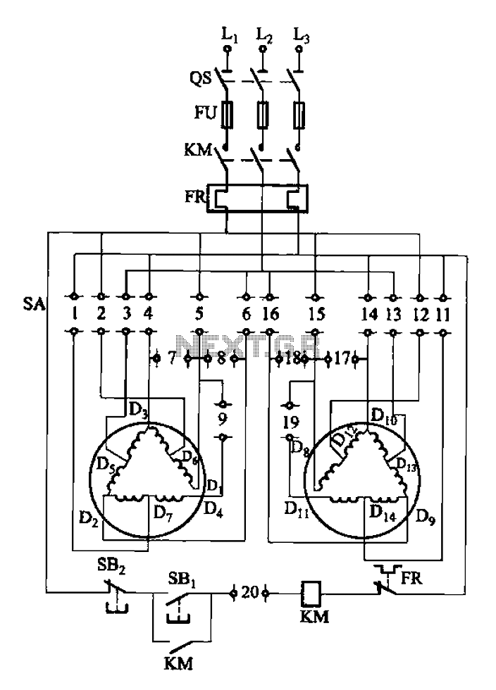
2Y-Y-2 - connection four-speed motor switch control circuit
The 3-119 circuit shown in the figure combines switch SA to realize the stator windings, specifically the 2, Y, and 2Y connections, which correspond to the motor speed n1.
The 3-119 circuit is designed to facilitate the control of motor speed...
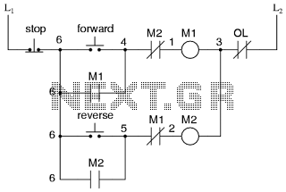
Motor control circuit for forward and reverse phase induction
This is the power diagram for motor forward and reverse operation. To change the motor direction, one polarity must be altered, for example, changing R to S. For detailed information, please refer to the following.
The described power diagram illustrates a...
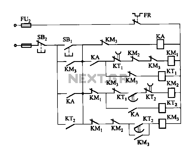
2 -Y- connection automatic three-speed motor acceleration control circuit
Figure 3-118 illustrates an automatic acceleration control circuit. This circuit employs a male contactor time relay, enabling the motor to start automatically at a low speed before transitioning to high-speed operation.
The automatic acceleration control circuit depicted in Figure 3-118 is...

5-motor hexapod circuit
This circuit has a long history, originating from an idea by Rich Piotter and later refined by Wilf Rigter and Bruce Robinson. The final result does not include the necessary motor drivers, which are typically H-bridge based, but presents a...
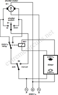
To Automate Rolling Shutter Motor
To automate the opening and closing of a rolling shutter using a time-controlled switch, additional wiring will be necessary.
To implement an automated system for a rolling shutter, a time-controlled switch can be utilized to manage the operation of the shutter....
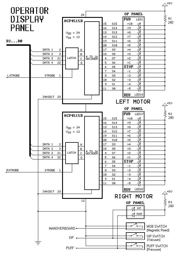
Dual-Motor SIP&PUFF Controlled Kayak System
The YouTube video below demonstrates the quick and easy setup of the system at the launch site.
The provided description indicates a focus on the efficiency of system installation at a launch site, as showcased in a YouTube video. In an...

Three-phase squirrel cage motor running single phase connection circuit
The circuit connection is illustrated in figures a and b. In figure a, a star-shaped winding is used with shunt capacitance, while figure b depicts a triangular winding with capacitance connected in parallel. The working capacitance (Cc) is calculated using...