


The use of self-induced emf achieve instant protection circuits
#self-induced emf
#instant protection
#motor
#power failure
#shutdown protection
#circuit protection
#electromotive force
#inductive load
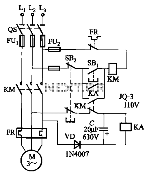
Description: The circuit illustrated in Figure 3-73 is designed to utilize the power generated by instantaneous power failures, specifically the self-induced electromotive force (emf) produced by the motor, to implement an immediate shutdown protection mechanism. During a momentary power outage, the contact KM loses power and releases, allowing the motor to continue rotating due to its inertia. At the same time, the normally closed auxiliary contact of KM remains closed, allowing the motor's self-induced emf to pass through diode VD and energize the DC relay KA. Once KA is energized, its normally open contact closes. When power is restored, the contactor KM receives electrical power, engages its self-locking mechanism, and reconnects the motor to the power supply for operation.
The circuit operates effectively as a protective measure against sudden power interruptions. The self-induced emf generated by the motor during a power loss is crucial for maintaining operation continuity. The use of diode VD is essential to prevent backflow of current, ensuring that the relay KA receives the necessary power to activate without interference from other circuit components.
Upon the loss of power, contact KM disengages, but the inertia of the motor allows it to continue rotating momentarily. The auxiliary contact, which remains closed during this event, permits the self-induced emf to energize the relay KA. This relay serves as a crucial link in the circuit, allowing the motor to remain operational for a brief period despite the absence of external power.
Once the power supply is restored, the contactor KM is re-energized, engaging its self-locking feature. This mechanism ensures that the motor is automatically reconnected to the power supply without the need for manual intervention, thus enhancing operational efficiency and reducing downtime. The design is particularly beneficial in applications where uninterrupted operation is critical, such as in industrial machinery and automated systems.
Overall, this circuit configuration effectively combines inertia, self-induced emf, and relay mechanisms to safeguard against power failures, ensuring that essential systems remain operational or can quickly resume operation after a power interruption. Circuit shown in Figure 3-73. The line is to use the power of instantaneous power failure, the self-induced emf generated by the motor to implement now instant shutdown protect ion. When momentary power outage, contact KM loss of power release, power machine for inertial rotation, while KM normally closed auxiliary contact is closed, the motor V, W and white self-induced emf through diode VD to the DC relay is powered KA. KA is energized, the normally open contact closure, if it when the power supply has been restored, the contactor KM obtain electric suction combined self- locking, the motor re-connect the power running.
The circuit operates effectively as a protective measure against sudden power interruptions. The self-induced emf generated by the motor during a power loss is crucial for maintaining operation continuity. The use of diode VD is essential to prevent backflow of current, ensuring that the relay KA receives the necessary power to activate without interference from other circuit components.
Upon the loss of power, contact KM disengages, but the inertia of the motor allows it to continue rotating momentarily. The auxiliary contact, which remains closed during this event, permits the self-induced emf to energize the relay KA. This relay serves as a crucial link in the circuit, allowing the motor to remain operational for a brief period despite the absence of external power.
Once the power supply is restored, the contactor KM is re-energized, engaging its self-locking feature. This mechanism ensures that the motor is automatically reconnected to the power supply without the need for manual intervention, thus enhancing operational efficiency and reducing downtime. The design is particularly beneficial in applications where uninterrupted operation is critical, such as in industrial machinery and automated systems.
Overall, this circuit configuration effectively combines inertia, self-induced emf, and relay mechanisms to safeguard against power failures, ensuring that essential systems remain operational or can quickly resume operation after a power interruption. Circuit shown in Figure 3-73. The line is to use the power of instantaneous power failure, the self-induced emf generated by the motor to implement now instant shutdown protect ion. When momentary power outage, contact KM loss of power release, power machine for inertial rotation, while KM normally closed auxiliary contact is closed, the motor V, W and white self-induced emf through diode VD to the DC relay is powered KA. KA is energized, the normally open contact closure, if it when the power supply has been restored, the contactor KM obtain electric suction combined self- locking, the motor re-connect the power running.
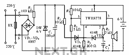
Multi power failure alarm circuit
The circuit functions as an AC blown fuse alarm. When the fuse (BX) is intact, 220 V AC voltage passes through a bridge rectifier composed of diodes VD1 to VD4. Resistor R1 limits the current, and the output is converted...
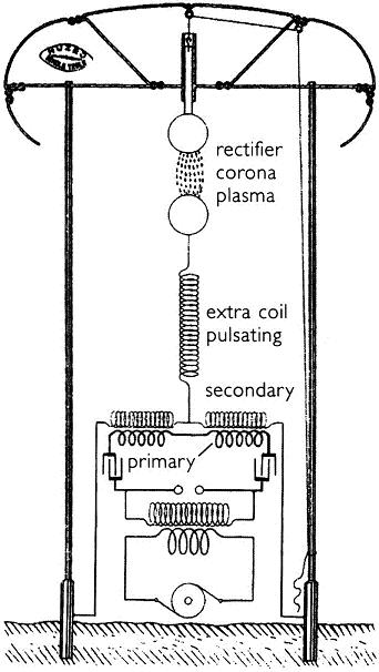
Gray Tube Replication 85
The information regarding operating the motor without the tubes is new to the individual. There is a desire to learn more about this subject.
The operation of a motor without the use of tubes can be a significant topic in the...

Two-speed motor stator winding 2Y-2Y connection
As illustrated in Figure 3-105, this diagram depicts the lead wiring configuration for a two-speed motor stator with a 2Y/2Y connection.
The two-speed motor stator wiring diagram is essential for understanding the configuration and operation of the motor. In this setup,...
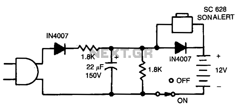
Power-faiwre-alarm
When the power is turned off, the alarm activates when switch S1 is closed. The 12-V battery remains charged when the circuit is connected and the switch is in the "on" position.
The described circuit features an alarm system that operates...
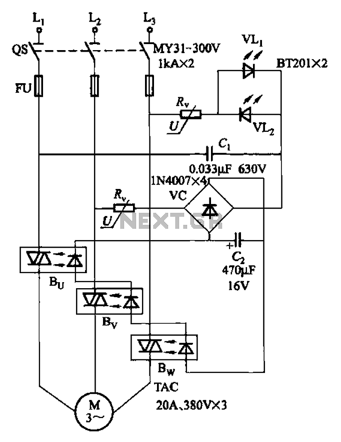
Three-way operation allows the motor-controlled circuits
The circuit depicted in Figure 3-93 is integrated with an optical phase sequence protection relay.
The circuit in question is designed to provide phase sequence protection using an optical relay mechanism. Optical phase sequence protection relays are crucial in applications where...
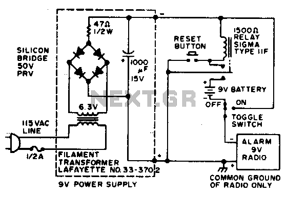
Power failure alarm
In the event of a power failure, the radio alarm activates without producing a loud siren, bell, or whistle. The alarm remains active even after power is restored and will continue until the RESET button is pressed.
The described circuit functions...
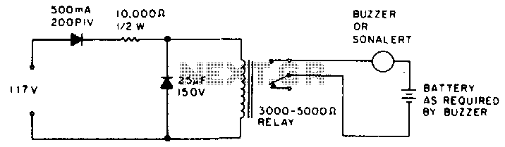
Power failure alarm
While the power is on, the relay remains open; however, when the power fails, the contacts of the buzzer circuit close.
The described circuit involves a relay and a buzzer, functioning in a power-dependent manner. In normal operation, when power is...
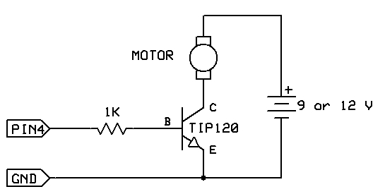
motor switch led circuit
The strategy involves assembling the circuit in stages, testing each component as it is integrated. Once all connections are established and can be controlled or read correctly by the computer, the main program can be developed with assurance that all...
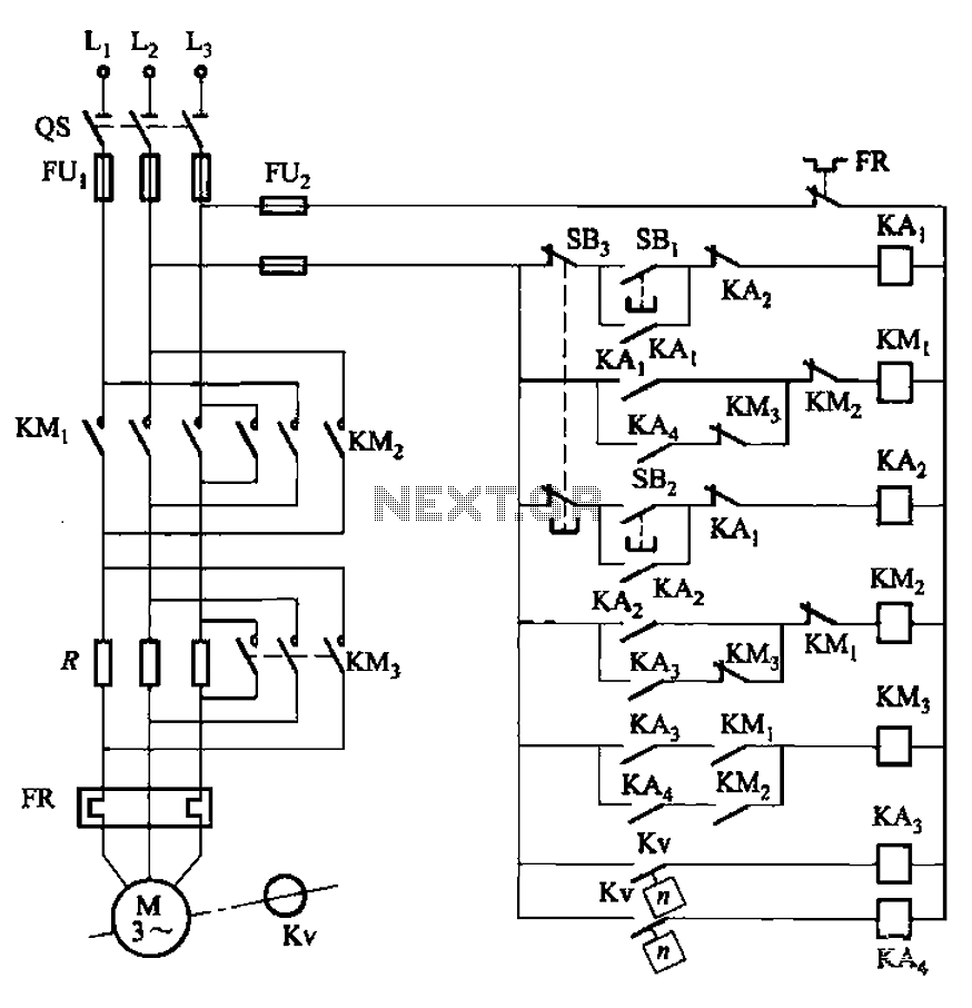
Three reversing operation of the reverse brake circuit
The circuit illustrated in Figure 3-130 differs from the circuit in Figure 3-129 in that when the stop button SB3 is pressed, the electric motor initiates braking. Furthermore, during both the startup and braking phases, the motor power lines are...