


The Z-bridge
#74F139
#motor driver
#transistors
#resistors
#current limit
#circuit board
#DIY
#peak current
#cost-effective
#hobby electronics
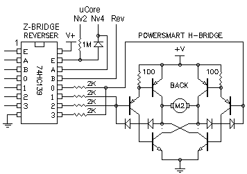
Description: The total cost will be approximately US$10, which will save space on the circuit board. The design is efficient, but space constraints and budget considerations are a concern. It is possible to eliminate all transistors and resistors if the motors do not draw excessive current. Only a 74F139 or 74S139 chip is required, excluding the LS version. This chip can deliver peak currents up to 10mA for brief periods (less than 1 second) and can only supply one output at a time under normal operating conditions. The extent of operational limits in this configuration is uncertain. While the design is straightforward, it effectively conveys the intended functionality.
The proposed circuit design focuses on optimizing component usage and minimizing costs while maintaining functionality. The use of the 74F139 or 74S139 chip is critical, as it is capable of handling the necessary logic operations without the additional complexity of transistors and resistors, provided that the motors connected do not exceed the current limits. The choice of the 74F139/S139 over the LS version is essential due to its higher speed and lower power consumption characteristics.
In this configuration, the chip operates in a way that allows for the control of multiple outputs, albeit one at a time, which is sufficient for many applications where sequential control is acceptable. The chip's ability to deliver peak currents of 10mA for short durations indicates that it can handle transient loads effectively, making it suitable for applications where brief bursts of current are required without overheating or damaging the circuit.
When designing the circuit board, careful consideration should be given to the layout to ensure that the chip is adequately supported by power and ground connections, minimizing the potential for noise and ensuring reliable operation. Additionally, it is advisable to include bypass capacitors close to the power pins of the chip to stabilize the voltage supply during peak current demands.
Overall, this design emphasizes simplicity and cost-effectiveness while ensuring that the essential functionalities are retained, making it suitable for applications where budget constraints and space limitations are critical.Altogether it will cost about US$ 10 and much room on my circuit board. The design is really great but i don`t have to room for it and i like to spend less. You can drop all off the transistors and resistors if your motors don`t drain too much current. You only need a 74F139 or 74S139 NOT the LS version. The chip can provide peak currents up to 10 0mA for a short time (<1 second) and to one output at a time. This is for normal connections. I don`t know how far you can go with this misbehavior. It`s nothing special, but you get the idea how it is done.
The proposed circuit design focuses on optimizing component usage and minimizing costs while maintaining functionality. The use of the 74F139 or 74S139 chip is critical, as it is capable of handling the necessary logic operations without the additional complexity of transistors and resistors, provided that the motors connected do not exceed the current limits. The choice of the 74F139/S139 over the LS version is essential due to its higher speed and lower power consumption characteristics.
In this configuration, the chip operates in a way that allows for the control of multiple outputs, albeit one at a time, which is sufficient for many applications where sequential control is acceptable. The chip's ability to deliver peak currents of 10mA for short durations indicates that it can handle transient loads effectively, making it suitable for applications where brief bursts of current are required without overheating or damaging the circuit.
When designing the circuit board, careful consideration should be given to the layout to ensure that the chip is adequately supported by power and ground connections, minimizing the potential for noise and ensuring reliable operation. Additionally, it is advisable to include bypass capacitors close to the power pins of the chip to stabilize the voltage supply during peak current demands.
Overall, this design emphasizes simplicity and cost-effectiveness while ensuring that the essential functionalities are retained, making it suitable for applications where budget constraints and space limitations are critical.Altogether it will cost about US$ 10 and much room on my circuit board. The design is really great but i don`t have to room for it and i like to spend less. You can drop all off the transistors and resistors if your motors don`t drain too much current. You only need a 74F139 or 74S139 NOT the LS version. The chip can provide peak currents up to 10 0mA for a short time (<1 second) and to one output at a time. This is for normal connections. I don`t know how far you can go with this misbehavior. It`s nothing special, but you get the idea how it is done.
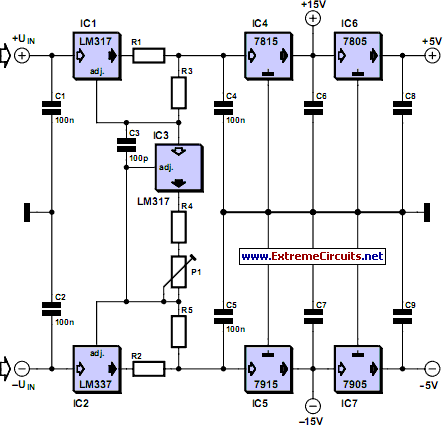
Adjustable Current Limit For Dual Power Supply
This current-limiting circuit, illustrated as part of a small bench power supply, can be utilized with any dual-rail current source. The section of the circuit to the left limits the current at the input to the dual voltage regulator (IC4...

Music Driven Motor Schematic
Music Driven Motor Schematic. The geared motor drives the stem of a dancing flower to the beat of music.
The music-driven motor schematic involves a geared motor that is activated in response to sound signals, specifically music. This design typically incorporates...
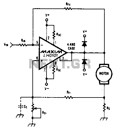
Constant-speed-motor-driver
When the torque load on the motor increases, its current also rises. This increase in current is detected across Rs, and positive feedback is applied to the noninverting terminal of the LH0101, which in turn raises the motor voltage to...

turret diy
For maximum mini-security, this RC Tupperware Turret delivers a formidable deterrent against food theft. While it lacks motion sensors, potential food thieves will think twice before attempting to swipe baked goods. This 11-hour project, designed by Chris of PyroElectro, emphasizes...
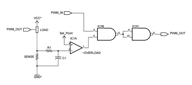
Custom Motor Driver
This chapter was removed from Applied Robotics 2 due to space constraints. It addresses general motor control issues and details the construction of a 5-amp motor driver. The principles discussed can be applied to larger motor controllers. Although commercially available...
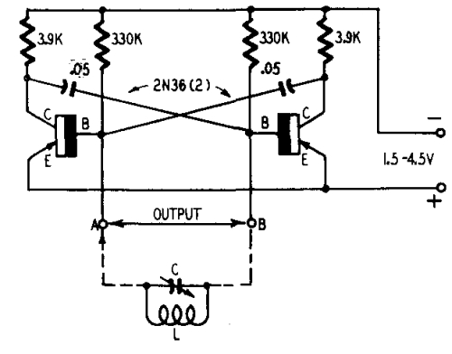
Oscillators and Triggers
Transistors are increasingly being utilized in various applications. Many circuits employing transistors have been developed based on previous designs that used vacuum tubes. The following chapters present unique applications that leverage the advantageous properties of transistors. The described circuits are...
Lie detector
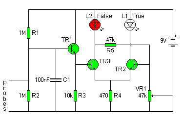
The circuit diagram of the Lie Detector is illustrated above. It consists of three transistors (TR1 to TR3), a capacitor (C1), two lights or LEDs (L1 & L2), five resistors (R1 to R5), and a variable resistor (VR1). This circuit...
Crescendo ampilifier elektor1982
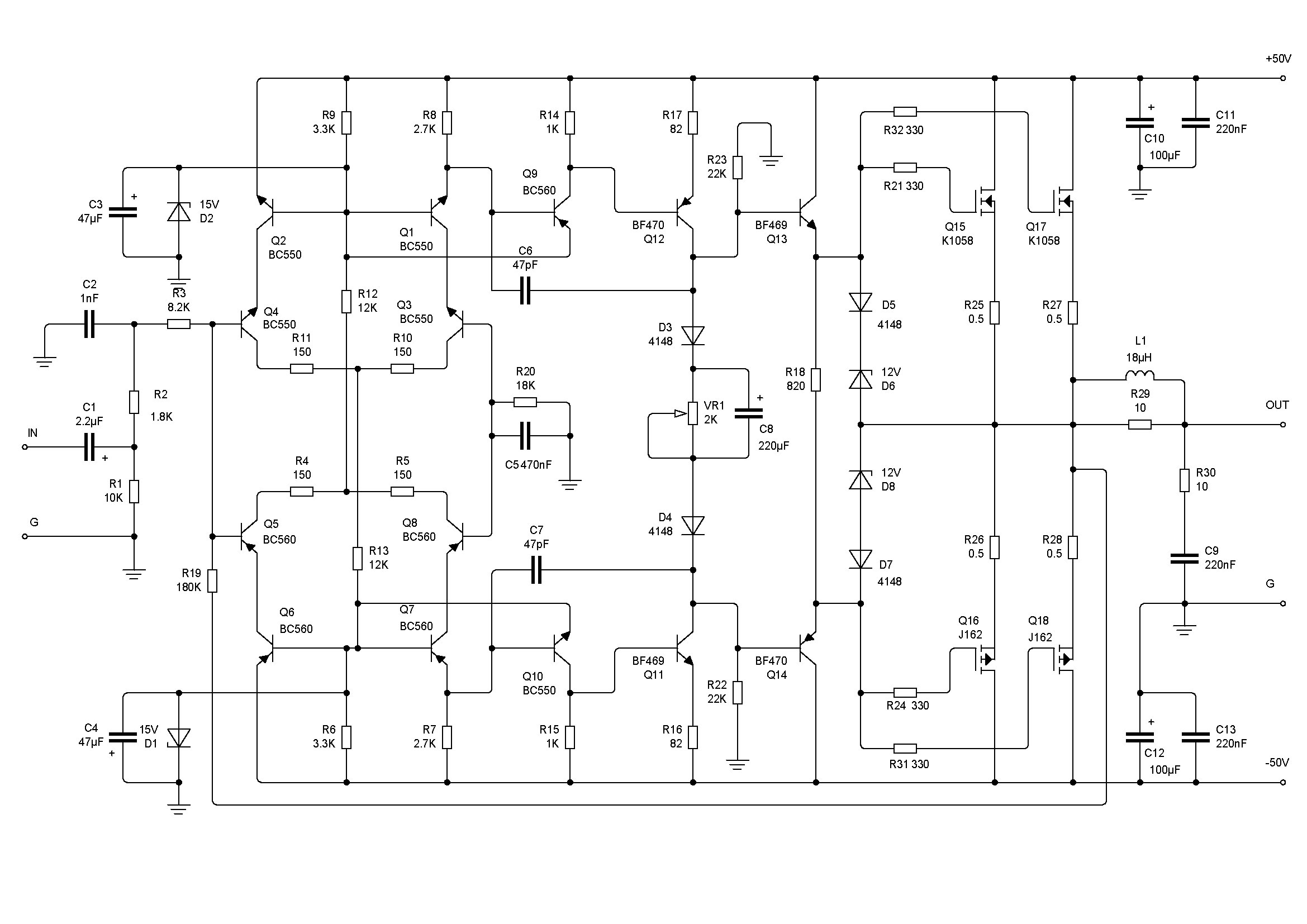
The Elector Crescendo was the first DIY amplifier that was not a kit. The design was sourced from the Elector magazines available at a local library.
The Elector Crescendo is an innovative audio amplifier designed for DIY enthusiasts. It features a...
progosc
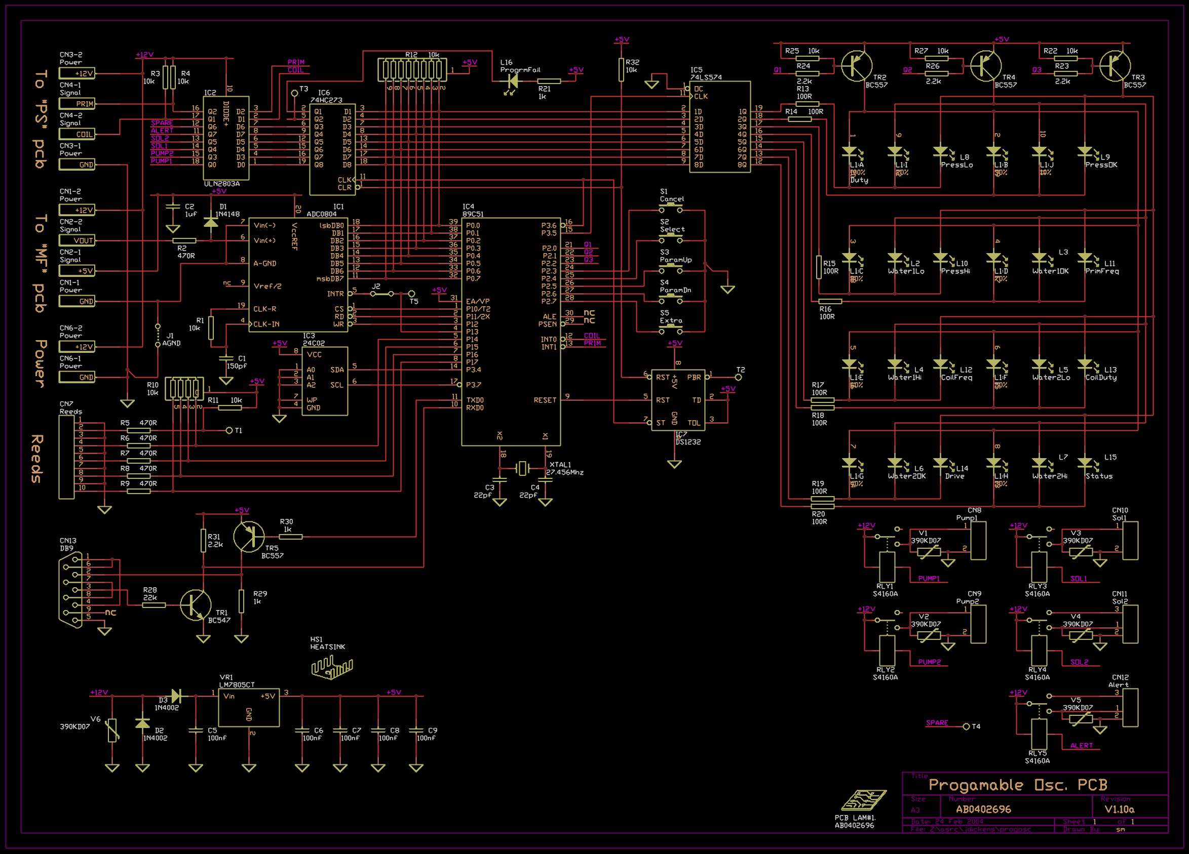
The objective of this project was to create cost-effective electronics that could be assembled by a small, informal PCB manufacturing plant in India, easily repaired, and produced with minimal setup. "Jellybean" (common, generic, low-cost) parts were utilized wherever possible. Although...