


Three-phase six-step motor control circuit diagram composed of MC33035
#three-phase
#motor control
#MC33035
#Darlington
#full-wave
#six-step
#open loop
#power switching
#controller
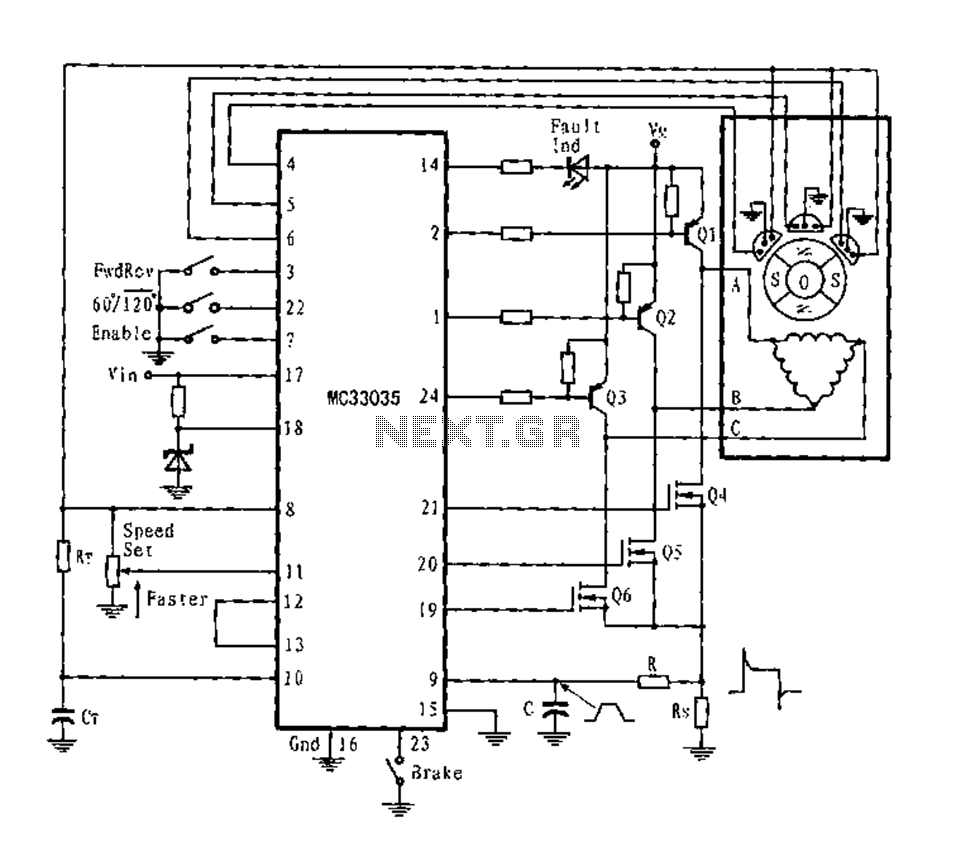
Description: The application circuit is a three-phase full-wave six-step driving circuit for an open-loop motor controller. It features a power switching transistor of the Darlington type, specifically PNP, while the lower power switching transistors are N-channel power MOSFETs. Each device incorporates parasitic clamping diodes, which facilitate the return of stator inductive energy. The output can drive either a triangular or star connection of the stator when using a separate power supply, and it can also drive a Y-connected neutral ground. At any given rotor position, only one of the top and bottom power switches (belonging to different totem poles) is active, enabling rational allocation to switch the stator windings from the power supply to ground at both ends, allowing for two-way or full-wave current. Leading edge spikes often occur in the current waveform, resulting in limiting errors. These spikes can be mitigated by incorporating a peak RC filter in series with the current detection input. Additionally, a low sense resistor (Rs) also aids in reducing spikes.
The three-phase full-wave six-step motor controller circuit is designed to efficiently manage the operation of an open-loop motor. The PNP Darlington transistors serve as the primary power switches, providing high current gain and facilitating the control of larger currents necessary for motor operation. The inclusion of N-channel power MOSFETs as lower power switches is critical due to their high efficiency and fast switching capabilities, which contribute to the overall performance of the circuit.
Each transistor within the circuit is equipped with parasitic clamping diodes. These diodes are essential for managing the inductive kickback generated by the stator coils during operation, allowing the energy to be returned to the power supply rather than dissipating as heat. This feature enhances the efficiency of the motor controller and prolongs the lifespan of the components.
The circuit's output configuration allows for flexibility in connecting the stator windings. By supporting both triangular and star configurations, the circuit can adapt to various motor designs and application requirements. The option to connect to a Y-neutral ground further enhances the circuit's versatility, enabling it to operate effectively under different electrical conditions.
In operation, at any rotor position, only one power switch from each totem pole is activated, ensuring that the circuit maintains optimal control over the motor. This selective switching allows for the efficient management of current flow through the stator windings, facilitating two-way or full-wave current operation. Such control is vital for achieving smooth motor performance and minimizing vibration.
To address the issue of leading edge spikes in the current waveform, which can lead to limiting errors and affect the performance of the motor, a peak RC filter is incorporated into the design. This filter effectively smooths out transient spikes, ensuring a more stable current detection input. The use of a low sense resistor (Rs) further assists in reducing these spikes, enhancing the reliability and accuracy of the current sensing mechanism within the circuit.
Overall, this three-phase full-wave six-step motor controller circuit is a sophisticated solution for driving open-loop motors, combining effective power management with adaptive output configurations and robust spike suppression techniques.Fig application circuit is a three-phase full-wave six-step driving an open loop motor controller circuit connection diagram. Wherein the power switching transistor Darlington PNP type, the lower power switching transistors are N-channel power MOSFET. Since each device contain a parasitic clamping diodes, which can power the stator inductive energy returned. The output can drive triangular connection or star connection of the stator, if using a separate power supply, but also to drive the Y-connected neutral ground.
At any given rotor position, the circuit shown in Figure 3 are the only one at the top and bottom power switches (belonging to different totem poles) is valid. Thus, through the rational allocation can switch the stator windings from the power supply to ground at both ends, and allows two-way or full-wave current.
Since the leading edge spikes usually occur in the current waveform, and will result in limiting errors. Therefore, the class can be suppressed by the peak RC filter in series with a current detection input.
Meanwhile, Rs low sense resistor also help reduce spikes.
The three-phase full-wave six-step motor controller circuit is designed to efficiently manage the operation of an open-loop motor. The PNP Darlington transistors serve as the primary power switches, providing high current gain and facilitating the control of larger currents necessary for motor operation. The inclusion of N-channel power MOSFETs as lower power switches is critical due to their high efficiency and fast switching capabilities, which contribute to the overall performance of the circuit.
Each transistor within the circuit is equipped with parasitic clamping diodes. These diodes are essential for managing the inductive kickback generated by the stator coils during operation, allowing the energy to be returned to the power supply rather than dissipating as heat. This feature enhances the efficiency of the motor controller and prolongs the lifespan of the components.
The circuit's output configuration allows for flexibility in connecting the stator windings. By supporting both triangular and star configurations, the circuit can adapt to various motor designs and application requirements. The option to connect to a Y-neutral ground further enhances the circuit's versatility, enabling it to operate effectively under different electrical conditions.
In operation, at any rotor position, only one power switch from each totem pole is activated, ensuring that the circuit maintains optimal control over the motor. This selective switching allows for the efficient management of current flow through the stator windings, facilitating two-way or full-wave current operation. Such control is vital for achieving smooth motor performance and minimizing vibration.
To address the issue of leading edge spikes in the current waveform, which can lead to limiting errors and affect the performance of the motor, a peak RC filter is incorporated into the design. This filter effectively smooths out transient spikes, ensuring a more stable current detection input. The use of a low sense resistor (Rs) further assists in reducing these spikes, enhancing the reliability and accuracy of the current sensing mechanism within the circuit.
Overall, this three-phase full-wave six-step motor controller circuit is a sophisticated solution for driving open-loop motors, combining effective power management with adaptive output configurations and robust spike suppression techniques.Fig application circuit is a three-phase full-wave six-step driving an open loop motor controller circuit connection diagram. Wherein the power switching transistor Darlington PNP type, the lower power switching transistors are N-channel power MOSFET. Since each device contain a parasitic clamping diodes, which can power the stator inductive energy returned. The output can drive triangular connection or star connection of the stator, if using a separate power supply, but also to drive the Y-connected neutral ground.
At any given rotor position, the circuit shown in Figure 3 are the only one at the top and bottom power switches (belonging to different totem poles) is valid. Thus, through the rational allocation can switch the stator windings from the power supply to ground at both ends, and allows two-way or full-wave current.
Since the leading edge spikes usually occur in the current waveform, and will result in limiting errors. Therefore, the class can be suppressed by the peak RC filter in series with a current detection input.
Meanwhile, Rs low sense resistor also help reduce spikes.
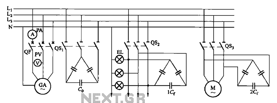
Asynchronous power wiring diagram
A three-phase squirrel cage induction motor is driven by a prime mover (such as diesel engines) and has asynchronous motor stator windings connected to the output end along with several capacitors for excitation power, enabling it to produce three-phase alternating...
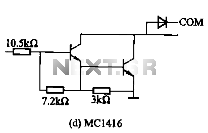
MC1411 series of Darlington Drive current internal structure
The MC1411 series features a Darlington drive current internal structure that offers small, consistent, and highly reliable parameters. This series is particularly effective for high-voltage applications and can directly drive loads such as relays and lights. It includes wheeling diodes...
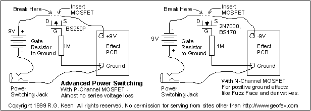
Advanced Power Switcher
If you are an effects builder or repairer, you know that it is a good idea to protect the circuitry in the effect from the consequences of a reversed battery. While many older effects can withstand a momentary reversal, some...
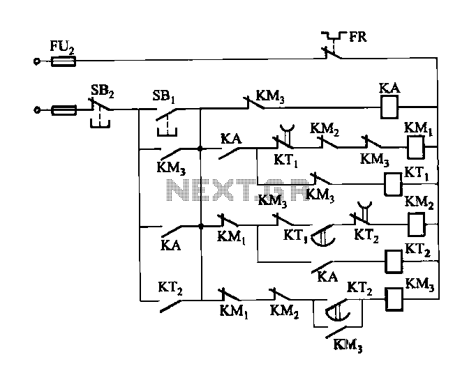
2 -Y- connection automatic three-speed motor acceleration control circuit
Figure 3-118 illustrates an automatic acceleration control circuit. This circuit employs a male contactor time relay, enabling the motor to start automatically at a low speed before transitioning to high-speed operation.
The automatic acceleration control circuit depicted in Figure 3-118 is...
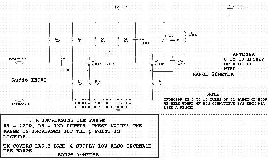
motor timer
The primary concept is to rotate the motor slightly every 15 seconds. A monofilament line conveys the motion to the ornament, which is wound by the motor and gradually unwinds as the ornament turns. The charging circuit includes a 1...
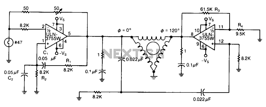
Three-phase ac motor driver 2
By varying either R1 or R2, the oscillator frequency can be adjusted over a narrow range. The R3/R4 ratio sets the second amplifier's gain to compensate for signal attenuation occurring in the phase shifters. The circuits can be driven from...
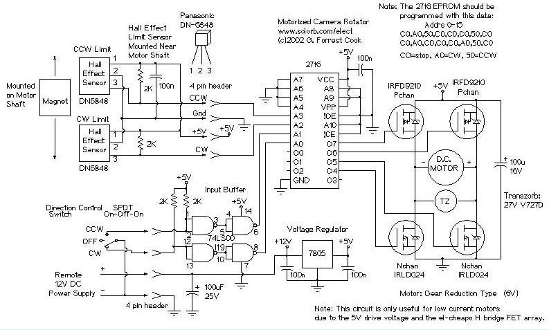
Motorized Video Camera Mount
The camera rotator circuit utilizes a 2716 EPROM to store a logic value table that governs the motor driver (H-bridge) circuit. The schematic illustrates the EPROM data. By employing the EPROM, a significant number of discrete gates are eliminated. The...

5-motor hexapod circuit
This circuit has a long history, originating from an idea by Rich Piotter and later refined by Wilf Rigter and Bruce Robinson. The final result does not include the necessary motor drivers, which are typically H-bridge based, but presents a...
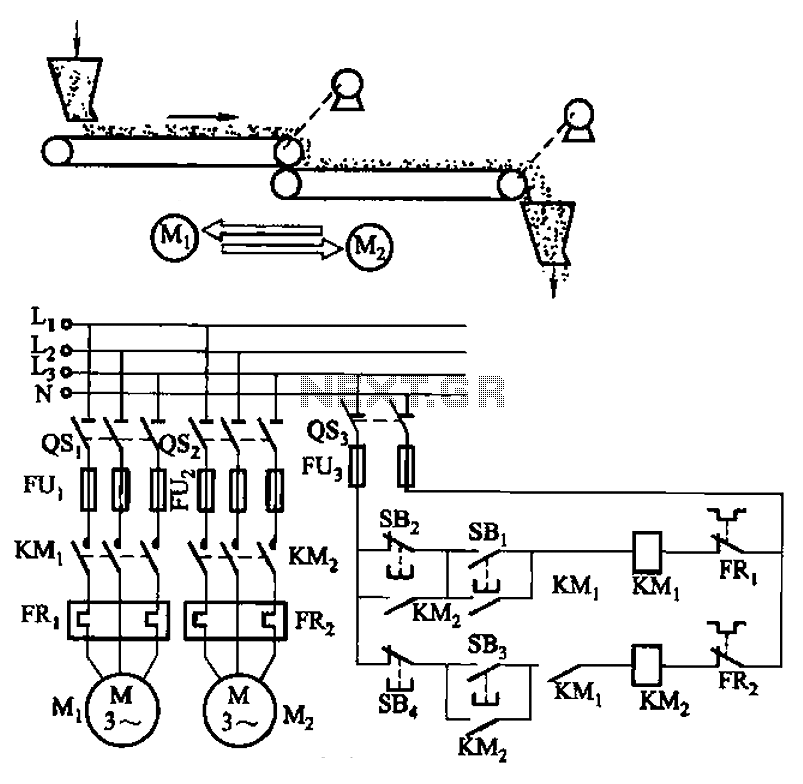
Belt conveyor interlock motor operation sequence control circuit
The circuit depicted in Figure 3-86 utilizes a line utilization time relay to control two motors, starting one before the other after an initial stall. The time relay KTi can be adjusted to modify the starting interval of the two...