


Two-Transistor DC Motor DriverCircuit Using The TIP32 Transistor
#transistor
#DC motor
#TIP32
#driver circuit
#motor driver
#two-transistor
#power control
#switching
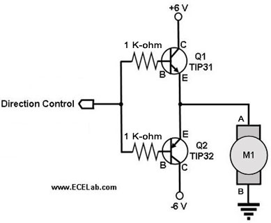
Description: The following circuit illustrates a two-transistor DC motor driver circuit diagram. This circuit utilizes the TIP32 transistor. Features: operates in...
The two-transistor DC motor driver circuit is designed to control the operation of a DC motor using two NPN transistors, which function as switches. The TIP32, a PNP transistor, is often employed in this configuration due to its capability to handle higher currents and voltages, making it suitable for driving motors.
In this circuit, the two NPN transistors are connected in a complementary push-pull configuration. When a control signal is applied to the base of the first NPN transistor, it turns on, allowing current to flow from the power supply through the motor and into the collector of the first transistor. This action causes the motor to rotate in one direction. Simultaneously, the second NPN transistor remains off, preventing current from flowing through it.
When the control signal is switched to the second transistor, it turns on, redirecting the current flow through the motor in the opposite direction, effectively reversing its rotation. This capability provides bidirectional control of the motor, which is essential for applications requiring precise movement, such as robotics or automated systems.
The circuit typically includes additional components, such as diodes for flyback protection, which safeguard the transistors from voltage spikes generated when the motor is switched off. Capacitors may also be included to filter out noise and stabilize the power supply.
Overall, this two-transistor DC motor driver circuit is a robust solution for controlling DC motors, offering simplicity in design while providing effective control over the motor's direction and speed.The following circuit shows about Two-Transistor DC Motor Driver Circuit Diagram . This circuit using the TIP32 Transistor. Features: runs in ..
The two-transistor DC motor driver circuit is designed to control the operation of a DC motor using two NPN transistors, which function as switches. The TIP32, a PNP transistor, is often employed in this configuration due to its capability to handle higher currents and voltages, making it suitable for driving motors.
In this circuit, the two NPN transistors are connected in a complementary push-pull configuration. When a control signal is applied to the base of the first NPN transistor, it turns on, allowing current to flow from the power supply through the motor and into the collector of the first transistor. This action causes the motor to rotate in one direction. Simultaneously, the second NPN transistor remains off, preventing current from flowing through it.
When the control signal is switched to the second transistor, it turns on, redirecting the current flow through the motor in the opposite direction, effectively reversing its rotation. This capability provides bidirectional control of the motor, which is essential for applications requiring precise movement, such as robotics or automated systems.
The circuit typically includes additional components, such as diodes for flyback protection, which safeguard the transistors from voltage spikes generated when the motor is switched off. Capacitors may also be included to filter out noise and stabilize the power supply.
Overall, this two-transistor DC motor driver circuit is a robust solution for controlling DC motors, offering simplicity in design while providing effective control over the motor's direction and speed.The following circuit shows about Two-Transistor DC Motor Driver Circuit Diagram . This circuit using the TIP32 Transistor. Features: runs in ..
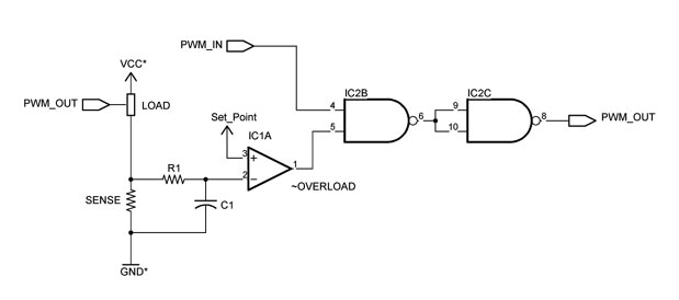
Custom Motor Driver
This chapter was removed from Applied Robotics 2 due to space constraints. It addresses general motor control issues and details the construction of a 5-amp motor driver. The principles discussed can be applied to larger motor controllers. Although commercially available...
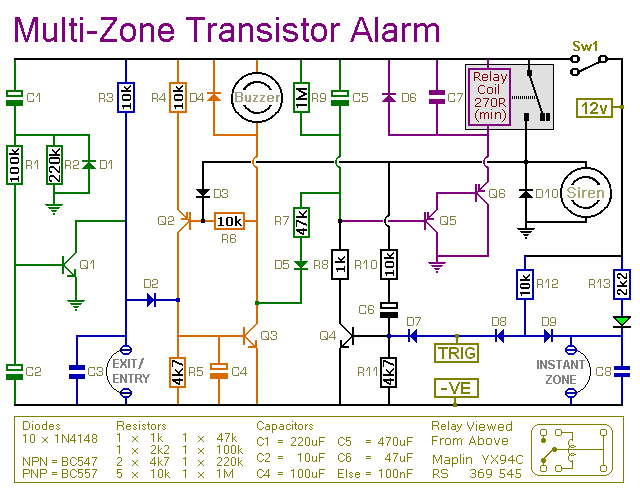
Multi-Zone Transistor-Based Intruder Alarm
This is a simple transistor-based burglar alarm circuit. Its features include automatic exit and entry delays, along with a timed bell cut-off and reset. It is designed to be used with standard types of normally-closed input devices such as magnetic...
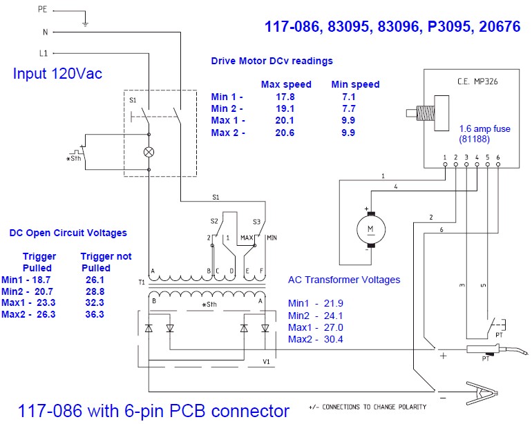
Need Help Deciphering Circuit Board Schematic
The wire speed DC motor consistently receives approximately 20 volts, irrespective of the switch position on the nozzle handle. The switch has been tested with an ohmmeter and functions properly. Even after disconnecting the switch from the circuit board, the...
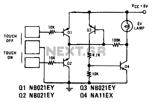
Touch-on-off-electronic-switch
Transistors Q1 and Q2 control latches Q3 and Q4 to switch on the lamp. A high resistance from touching the electrode biases Q1 or Q2 on, setting or resetting the latch.
In this circuit, transistors Q1 and Q2 function as input...
Bathroom Deoderizer Control
This device features a small DC motor fan situated above a container filled with deodorant liquid or gel, powered by a D cell battery. A photocell is integrated to deactivate the fan in low light conditions. An LED indicator flashes...
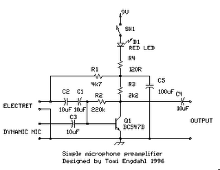
simple microphone preamplifier
The circuit is a simple one-transistor amplifier with an amplification factor of approximately 30-40 dB, which varies depending on the transistor, temperature, and voltage. The dynamic microphone input is a straightforward one-transistor amplifier circuit with no special features. LED D1...
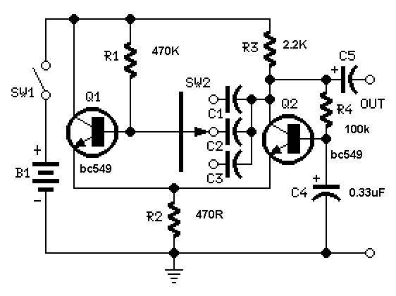
Simple Square wave Generator using transistors ~ Easy Electronics
A useful feature of this circuit is that the frequency can be changed by modifying the capacitor value. A switch can be added to select between various frequencies.
This circuit utilizes a capacitor in conjunction with an oscillator to determine its...
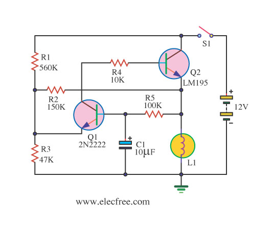
A lamp flasher circuit using transistors
If you require a small lamp that flashes for general use, there are numerous options available. Today, three lamp flasher circuits will be presented.
The three lamp flasher circuits can be designed using different components and configurations, each offering unique characteristics...
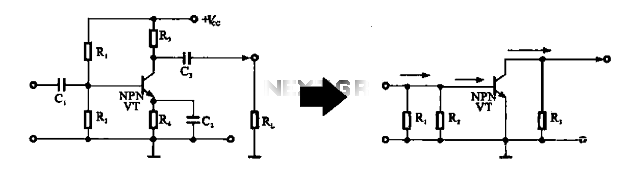
Alternating current voltage amplifier transistor
An alternating current voltage amplifier transistor AC path is described. In AC analysis, the internal resistance of the AC supply voltage source is low, which corresponds to a short circuit signal. Consequently, the alternating voltage terminal Vcc is considered to...