


typical circuit diagram of star delta
#star delta starter
#contactors
#overload relay
#timer
#starting current
#starting torque
#motor connection
#three-phase motor
#industrial motor control
#electrical circuits
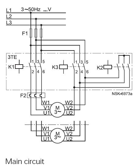
Description: This method reduces starting current and starting torque. The device typically consists of three contactors, an overload relay, and a timer for setting the duration in the star position (starting position). The motor must be delta connected during normal operation to utilize this starting method. The starting current is approximately 30% of the starting current during a direct-on-line (D.O.L) start, and the starting torque is reduced to about 25% of the torque available at a D.O.L start. This method is effective only when the application is lightly loaded at startup. If the motor is heavily loaded, there may not be sufficient torque to accelerate the motor to speed before switching to the delta position. For instance, when starting pumps and fans, the load torque is low initially and increases with the square of the speed. Upon reaching approximately 80-85% of the motor's rated speed, the load torque equals the motor torque, and acceleration halts. To achieve the rated speed, a transition to the delta position is necessary, which can often lead to significant current and transmission peaks. In some instances, the current peak may exceed that of a D.O.L start. Applications with load torque exceeding 50% of the motor's rated torque will not be able to utilize the start-delta starter.
The start-delta starting method is a widely used technique in industrial applications to mitigate the effects of high inrush current and torque during motor startup. This method employs a combination of contactors and a timer to manage the transition from a star (or wye) configuration to a delta configuration. In the star configuration, the motor windings are connected in such a way that the voltage across each winding is reduced, leading to a lower starting current and torque. This is particularly advantageous for applications with significant inrush currents, as it helps to protect the motor and associated equipment from damage.
The three contactors serve distinct purposes: one for the star connection, one for the delta connection, and one for the overload relay to monitor the motor's current and protect against overheating. The overload relay is critical in ensuring that the motor does not operate under excessive load conditions, which could lead to failure. The timer is programmed to maintain the star connection for a predetermined duration, allowing the motor to accelerate to a certain speed before switching to the delta configuration.
In applications such as pumps and fans, where the load torque is relatively low at startup, the start-delta method is particularly effective. The load torque increases with the square of the speed, which means that as the motor accelerates, it can handle the increasing load without exceeding its rated capacity. However, if the application involves higher load torques, exceeding 50% of the motor's rated torque, this starting method may not be suitable. In such cases, the motor may not achieve the necessary speed before transitioning to the delta configuration, resulting in insufficient torque to overcome the load.
It is essential to consider the specific requirements of the application when selecting a starting method. The start-delta starter is best suited for applications with light to moderate loads, while direct-on-line starters or soft starters may be more appropriate for heavier loads. Proper selection and implementation of the starting method can lead to improved efficiency, reduced wear on the motor, and extended operational life of the equipment.This is a starting method that reduces the starting current and starting torque. The device normally consists of three contactors, an overload relay and a timer for setting the time in the star-position (starting position). The motor must be delta connected during a normal run, in order to be able to use this starting method.
The received starting current is about 30 % of the starting current during direct on line start and the starting torque is reduced to about 25 % of the torque available at a D. O. L start. This starting method only works when the application is light loaded during the start. If the motor is too heavily loaded, there will not be enough torque to accelerate the motor up to speed before switching over to the delta position.
When starting up pumps and fans for example, the load torque is low at the beginning of the start and increases with the square of the speed. When reaching approx. 80-85 % of the motor rated speed the load torque is equal to the motor torque and the acceleration ceases.
To reach the rated speed, a switch over to delta position is necessary, and this will very often result in high transmission and current peaks. In some cases the current peak can reach a value that is even bigger than for a D. O. L start. Applications with a load torque higher than 50 % of the motor rated torque will not be able to start using the start-delta starter.
The start-delta starting method is a widely used technique in industrial applications to mitigate the effects of high inrush current and torque during motor startup. This method employs a combination of contactors and a timer to manage the transition from a star (or wye) configuration to a delta configuration. In the star configuration, the motor windings are connected in such a way that the voltage across each winding is reduced, leading to a lower starting current and torque. This is particularly advantageous for applications with significant inrush currents, as it helps to protect the motor and associated equipment from damage.
The three contactors serve distinct purposes: one for the star connection, one for the delta connection, and one for the overload relay to monitor the motor's current and protect against overheating. The overload relay is critical in ensuring that the motor does not operate under excessive load conditions, which could lead to failure. The timer is programmed to maintain the star connection for a predetermined duration, allowing the motor to accelerate to a certain speed before switching to the delta configuration.
In applications such as pumps and fans, where the load torque is relatively low at startup, the start-delta method is particularly effective. The load torque increases with the square of the speed, which means that as the motor accelerates, it can handle the increasing load without exceeding its rated capacity. However, if the application involves higher load torques, exceeding 50% of the motor's rated torque, this starting method may not be suitable. In such cases, the motor may not achieve the necessary speed before transitioning to the delta configuration, resulting in insufficient torque to overcome the load.
It is essential to consider the specific requirements of the application when selecting a starting method. The start-delta starter is best suited for applications with light to moderate loads, while direct-on-line starters or soft starters may be more appropriate for heavier loads. Proper selection and implementation of the starting method can lead to improved efficiency, reduced wear on the motor, and extended operational life of the equipment.This is a starting method that reduces the starting current and starting torque. The device normally consists of three contactors, an overload relay and a timer for setting the time in the star-position (starting position). The motor must be delta connected during a normal run, in order to be able to use this starting method.
The received starting current is about 30 % of the starting current during direct on line start and the starting torque is reduced to about 25 % of the torque available at a D. O. L start. This starting method only works when the application is light loaded during the start. If the motor is too heavily loaded, there will not be enough torque to accelerate the motor up to speed before switching over to the delta position.
When starting up pumps and fans for example, the load torque is low at the beginning of the start and increases with the square of the speed. When reaching approx. 80-85 % of the motor rated speed the load torque is equal to the motor torque and the acceleration ceases.
To reach the rated speed, a switch over to delta position is necessary, and this will very often result in high transmission and current peaks. In some cases the current peak can reach a value that is even bigger than for a D. O. L start. Applications with a load torque higher than 50 % of the motor rated torque will not be able to start using the start-delta starter.
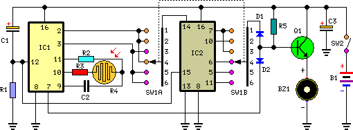
A Tan TimerCircuit
Six timing positions suited to different skin types; timing affected by sunlight intensity. This timer was designed for individuals seeking to achieve a tan.
The electronic timer circuit described is intended for use in tanning applications, specifically designed to cater to...
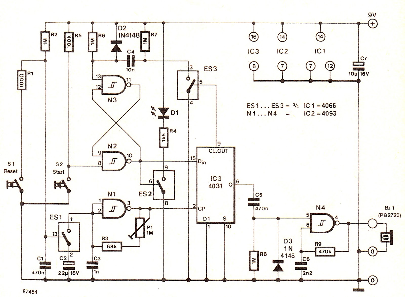
Bathroom Water Heater Timer
The electronic switch ES1 connects the frequency-determining capacitor to the input of clock oscillator N1. The logic level present at the Dm terminal of the integrated circuit is shifted to output Q at a speed defined by P1, allowing for...
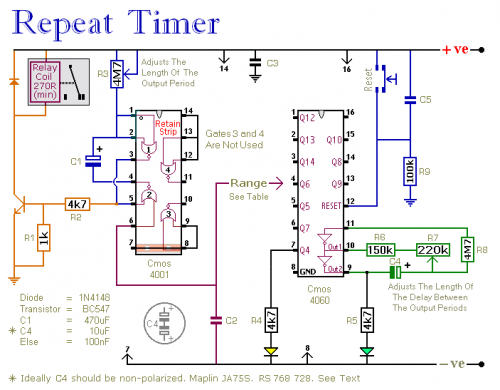
A Regularly Repeating Interval Timer
This circuit features an adjustable output timer capable of re-triggering at regular intervals. The output duration can range from a fraction of a second to half an hour or longer, with the ability to recur at intervals spanning from seconds...
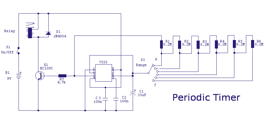
Periodic Timer
A switched timer with equal make and equal space periods timing adjustable from over 6 minutes to 38 minutes. This timer circuit is similar to the 5 to 30 minute timer except that when switch S1 is closed, the on/off...
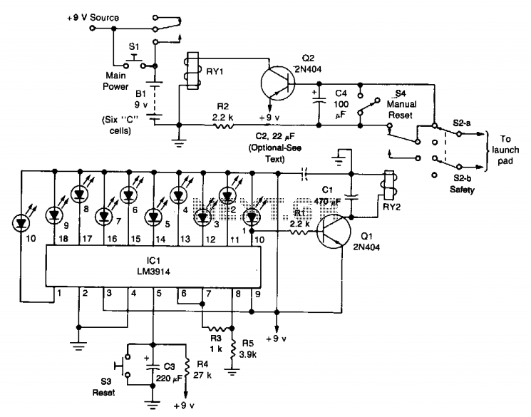
Model rocket launcher
The circuit comprises a launch timer and an automatic-off timer. Upon applying power to the integrated circuit (IC), the countdown LED sequence activates until all LEDs are illuminated. When the last LED (LED1) is fully lit, transistor Q1 enters saturation,...
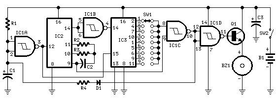
Jogging Timers
This circuit was developed in response to requests from visitors of this website for a timer that can emit a beep after one, two, three minutes, and so on, for jogging purposes. As illustrated in the circuit diagram, SW1 is...
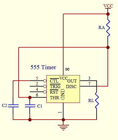
Timer circuit
The timer circuit is utilized in various projects and is primarily categorized into two types. The first type is an analog RC circuit, where the charging of the capacitor determines the timing of the circuit. This type has a larger...
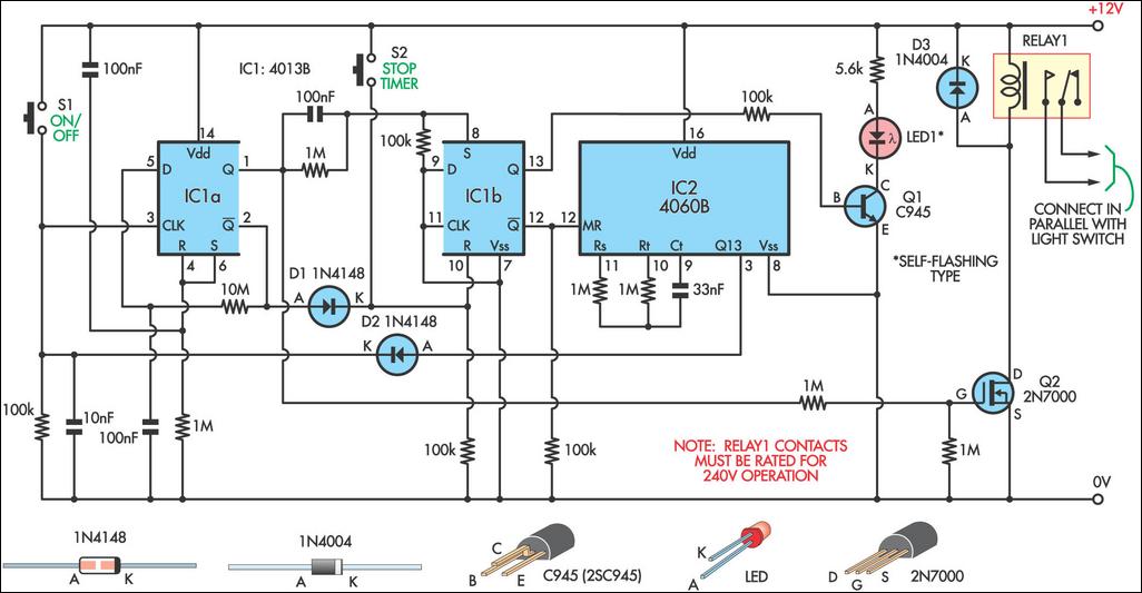
Switch Timer For Bathroom Light
This 9-minute timer switch can be utilized to control lighting in a toilet or bathroom. The timer is activated by pressing switch S1 and deactivated by pressing S1 again. If the timer is not manually turned off, the light will...
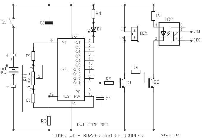
Timer with buzzer and optocoupler circuit
A small circuit designed for various time measurement applications. It features an audible sound signal from the buzzer BZ1 and has the capability to drive an external circuit through the optocoupler IC2, once the appropriate circuit is connected to contacts...