


Universal motor control with built in self timer
#universal motor
#SCR
#timer
#delay circuit
#commutator
#heavy load
#capacitance
#General Electric
#motor driver
#speed control
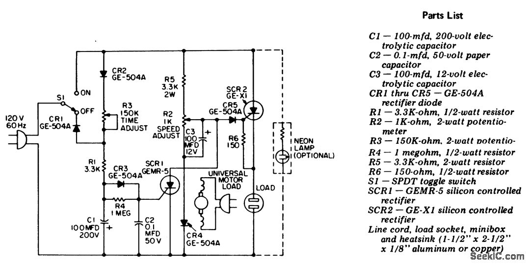
Description: Universal motor control with an integrated self-timer. This circuit is designed exclusively for use with motors that have commutators. When expecting heavy motor loads, it is advisable to replace the GE-X1 with a larger-rated C30B SCR for SCR2. To extend the time delay, increase the capacitance of capacitor C1 (courtesy of General Electric Company).
The universal motor control circuit described operates by regulating the power supplied to a commutator motor, allowing for precise control over the motor's speed and operation time. It incorporates a self-timer feature, which automatically disconnects the motor after a predetermined period, thus preventing overheating or damage due to prolonged operation.
The circuit typically includes a silicon-controlled rectifier (SCR) configuration, with SCR1 and SCR2 managing the power flow to the motor. SCR1 is responsible for the initial control, while SCR2 can be upgraded to a higher-rated component, such as the C30B SCR, to accommodate motors under heavy loads. This enhancement is critical for ensuring the reliability and longevity of the circuit when dealing with high current demands.
The timing mechanism is achieved through the use of capacitor C1, which, when adjusted, alters the time delay before the motor is turned off. Increasing the capacitance of C1 will extend the delay period, allowing for longer operational times before automatic shutdown occurs. This feature is particularly useful in applications where the motor must run for a specific duration without manual intervention.
Overall, this circuit provides a robust solution for controlling universal motors, with the flexibility to adapt to various operational requirements through component selection and configuration adjustments.Universal motor control with built-in self-timer. Use this circuit only with motors having commutators. If heavy motor loads are anticipated, use a larger-rated C30B SCR in place of the GE-X1 for SCR2. To increase the time delay increase the capacitance of 01 (courtesy General Electric Company).
The universal motor control circuit described operates by regulating the power supplied to a commutator motor, allowing for precise control over the motor's speed and operation time. It incorporates a self-timer feature, which automatically disconnects the motor after a predetermined period, thus preventing overheating or damage due to prolonged operation.
The circuit typically includes a silicon-controlled rectifier (SCR) configuration, with SCR1 and SCR2 managing the power flow to the motor. SCR1 is responsible for the initial control, while SCR2 can be upgraded to a higher-rated component, such as the C30B SCR, to accommodate motors under heavy loads. This enhancement is critical for ensuring the reliability and longevity of the circuit when dealing with high current demands.
The timing mechanism is achieved through the use of capacitor C1, which, when adjusted, alters the time delay before the motor is turned off. Increasing the capacitance of C1 will extend the delay period, allowing for longer operational times before automatic shutdown occurs. This feature is particularly useful in applications where the motor must run for a specific duration without manual intervention.
Overall, this circuit provides a robust solution for controlling universal motors, with the flexibility to adapt to various operational requirements through component selection and configuration adjustments.Universal motor control with built-in self-timer. Use this circuit only with motors having commutators. If heavy motor loads are anticipated, use a larger-rated C30B SCR in place of the GE-X1 for SCR2. To increase the time delay increase the capacitance of 01 (courtesy General Electric Company).
Two-Sheets Detector
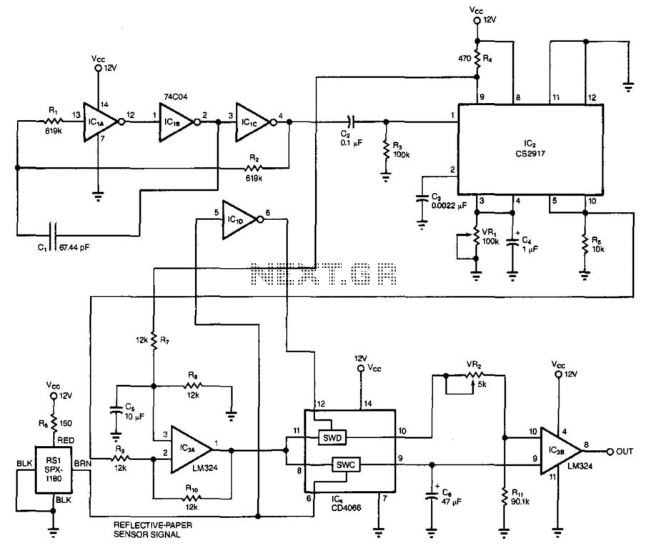
This circuit utilizes the principle of capacitance between two plates to detect when multiple sheets of paper are placed between the sensing electrodes simultaneously. CI is the sensing capacitor, composed of two plates measuring 2 inches by 15 inches with...
Jogging Timer
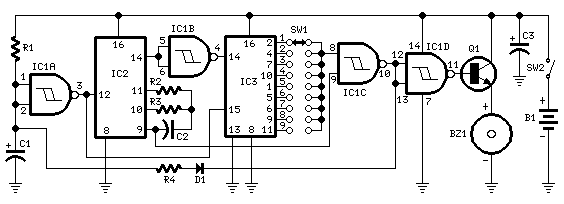
This circuit was developed in response to requests from visitors for a timer that can emit a beep after intervals of one, two, three minutes, and so forth, suitable for jogging purposes. As illustrated in the circuit diagram, SW1 is...
Jogging TimerCircuit
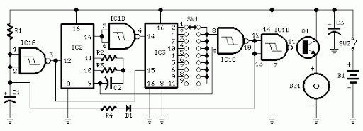
3V battery-powered circuit that emits a beep after a fixed delay of several minutes. This circuit was created in response to requests from users seeking a timer functionality.
The described circuit operates on a 3V power supply, making it suitable for...
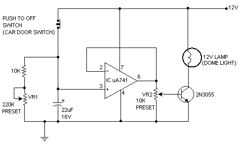
Auto Light Time/ Dimmer
A light timer/dimmer, similar to those found in dome lights, is desired, but guidance on how to begin the project is needed.
A light timer/dimmer circuit is designed to control the brightness of a light source and to provide a timed...
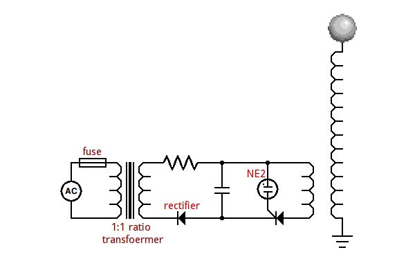
SCR to make a small solid state tesla coil
An SCR (Silicon Controlled Rectifier) functions similarly to a diode, allowing current to flow in one direction and can be turned on; it remains in this state until the power is interrupted. The query arises regarding its application in circuits,...
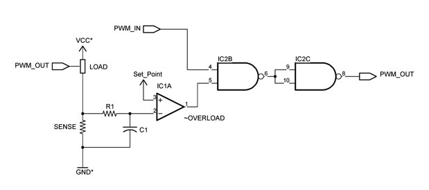
Custom Motor Driver
This chapter was removed from Applied Robotics 2 due to space constraints. It addresses general motor control issues and details the construction of a 5-amp motor driver. The principles discussed can be applied to larger motor controllers. Although commercially available...
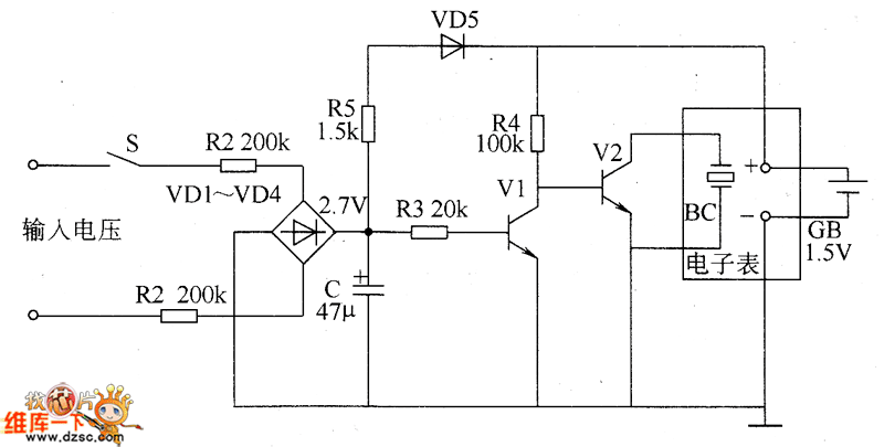
Cumulative timer circuit diagram
The cumulative timer circuit comprises resistor R1 and an internal crystal oscillator, represented in a chart. Resistors R1 and R2 are metal film types, while resistors R3 to R5 are rated at 1/8W and also of the metal film variety....
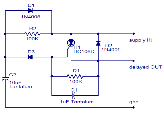
dc power delay based on scr
The circuit diagram presented illustrates a straightforward DC power delay circuit that utilizes a Silicon-Controlled Rectifier (SCR). This circuit is highly versatile and applicable in various scenarios. The operation is uncomplicated: when the input power is supplied, capacitor C2 charges...
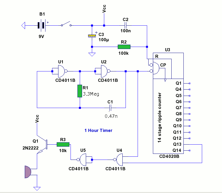
1 Hour Timer
Speaker relay delay controlling circuit for audio amplifier
The speaker relay delay control circuit is designed to protect audio amplifiers and speakers from potential damage caused by inrush current or transient signals during power-up or power-down sequences. This circuit typically employs...