


Using IRFP250 power tube H-bridge motor drive circuit
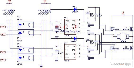
Description: The drive circuit for the electromotor comprises a FET bridge circuit, a FET base drive circuit, a current sensor for the motor drive circuit, and a relay. The FET bridge circuit primarily consists of four high-power MOSFETs, which must possess excellent switching characteristics, the ability to handle higher drive currents, and a long operational lifespan.
The drive circuit is designed to control the operation of an electromotor efficiently. The FET bridge circuit, utilizing four high-power MOSFETs, serves as the core component responsible for converting the input control signals into the appropriate motor drive signals. These MOSFETs are selected based on their switching speed, thermal management capabilities, and current handling specifications to ensure optimal performance and reliability.
The FET base drive circuit is essential for providing the necessary gate drive voltage to the MOSFETs, enabling them to switch on and off effectively. This circuit is typically designed to deliver sufficient gate drive current to ensure rapid switching, which minimizes heat generation and enhances overall efficiency. Proper gate drive design is critical to prevent issues such as cross-conduction and to ensure that the MOSFETs operate within their safe operating area.
The current sensor integrated into the motor drive circuit monitors the current flowing through the electromotor. This feedback mechanism is crucial for protecting the motor and drive circuit from overcurrent conditions, which can lead to damage. The current sensor provides real-time data that can be used for implementing control algorithms, such as current limiting and fault detection.
Additionally, the relay in the circuit serves as a protective element, allowing for the disconnection of the motor from the power supply in case of fault conditions or when the motor needs to be turned off safely. The relay is activated by control signals from the FET base drive circuit, ensuring that the motor can be engaged or disengaged as needed.
Overall, this drive circuit is designed to provide robust and efficient control of an electromotor, incorporating essential components that enhance performance, reliability, and safety in various applications.The drive circuit of electromotor includes a FET bridge circuit, FET base drive circuit,current sensor of motor drive circuit and the relay. FET bridge circuit mainly consists of four high-power MOSFET power tubes,it requires that the power tubes have good switching characteristics,can withstand higher drive current and have a long life.According to motor po..
The drive circuit is designed to control the operation of an electromotor efficiently. The FET bridge circuit, utilizing four high-power MOSFETs, serves as the core component responsible for converting the input control signals into the appropriate motor drive signals. These MOSFETs are selected based on their switching speed, thermal management capabilities, and current handling specifications to ensure optimal performance and reliability.
The FET base drive circuit is essential for providing the necessary gate drive voltage to the MOSFETs, enabling them to switch on and off effectively. This circuit is typically designed to deliver sufficient gate drive current to ensure rapid switching, which minimizes heat generation and enhances overall efficiency. Proper gate drive design is critical to prevent issues such as cross-conduction and to ensure that the MOSFETs operate within their safe operating area.
The current sensor integrated into the motor drive circuit monitors the current flowing through the electromotor. This feedback mechanism is crucial for protecting the motor and drive circuit from overcurrent conditions, which can lead to damage. The current sensor provides real-time data that can be used for implementing control algorithms, such as current limiting and fault detection.
Additionally, the relay in the circuit serves as a protective element, allowing for the disconnection of the motor from the power supply in case of fault conditions or when the motor needs to be turned off safely. The relay is activated by control signals from the FET base drive circuit, ensuring that the motor can be engaged or disengaged as needed.
Overall, this drive circuit is designed to provide robust and efficient control of an electromotor, incorporating essential components that enhance performance, reliability, and safety in various applications.The drive circuit of electromotor includes a FET bridge circuit, FET base drive circuit,current sensor of motor drive circuit and the relay. FET bridge circuit mainly consists of four high-power MOSFET power tubes,it requires that the power tubes have good switching characteristics,can withstand higher drive current and have a long life.According to motor po..
Switching Power Supply
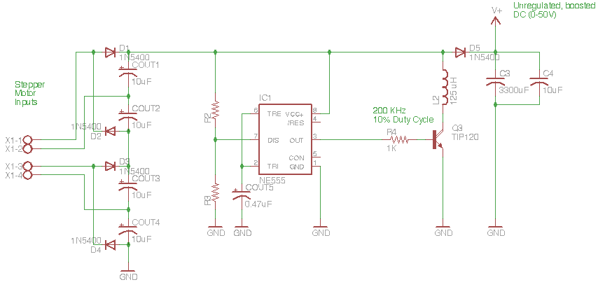
The circuit depicted in the schematic below represents an enhanced generator electronics system. It is an unregulated switcher designed to maximize sound output while ensuring prolonged CPU operation. This circuit efficiently transfers electrical energy from the generator, outperforming traditional rectifier...
JB-22 transistor relay circuit
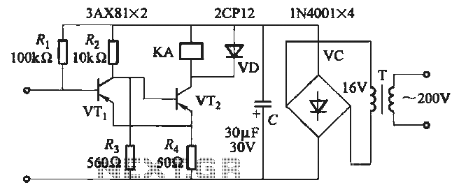
When the input is disconnected, the transistor VTi conducts, while VTz is in cutoff, causing relay KA to release. When the input is shorted, VTi is cut off, VTz conducts, and relay KA is activated.
In this circuit configuration, the operation...
Can effectively guarantee the auto-voltage starting circuit main contact of extinction
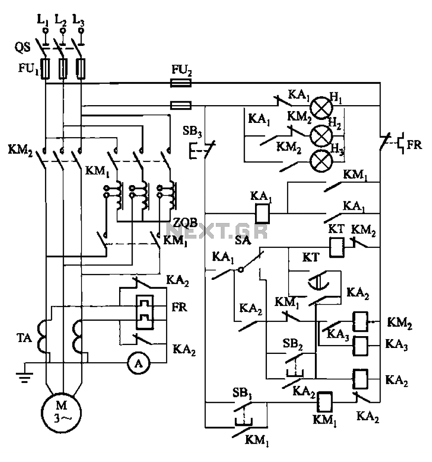
The circuit illustrated in Figure 3-56 features both manual and automatic start-up modes. It incorporates two relays, KA2 and KA3, within the control loop. The circuit design ensures that KM1 is cut off before and after activating KM2. A main...
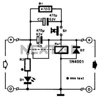
Relay Fuse For Power Supplies Circuit
A method of adding overload protection to a power supply using a relay is shown. In each circuit, the relay must be reset by a momentary switch using a charge on capacitor C2. This prevents overload if the short still...
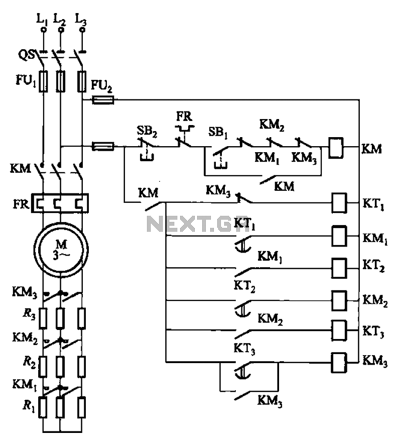
Time relay three-start circuit
The circuit depicted in Figure 3-159 employs complementary operation three times along with three relay contacts. This is followed by the automatic elimination of the rotor circuit resistance levels, ultimately reducing the rotor winding variable resistor to zero (fully shorted),...
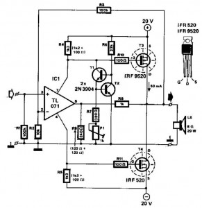
20w mosfet power amplifier
This audio power amplifier employs two complementary MOSFETs (IRF9520 and IRF520) to provide up to 20W output into an 8-ohm speaker. A TL071 operational amplifier functions as the input amplifier. The MOSFETs require heatsinking with a thermal resistance of better...
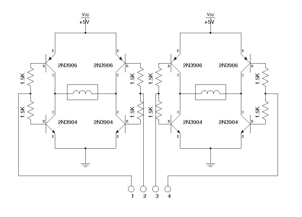
A Simple Dual H-Bridge
An H-bridge is commonly utilized for controlling DC motors and stepper motors. When managing a bipolar stepper motor, two complete H-bridges are required. Numerous H-bridge integrated circuits (ICs) such as the L298, MPC17529, and SN754410 (a quad half H-bridge) are...
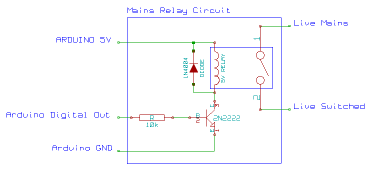
mains ac relay module
This mains AC relay module utilizes 5V relays that can be powered directly from an Arduino and can switch 230V. A basic energy monitoring and control system has been constructed using an Arduino 2009, off-the-shelf wireless remote control sockets, and...
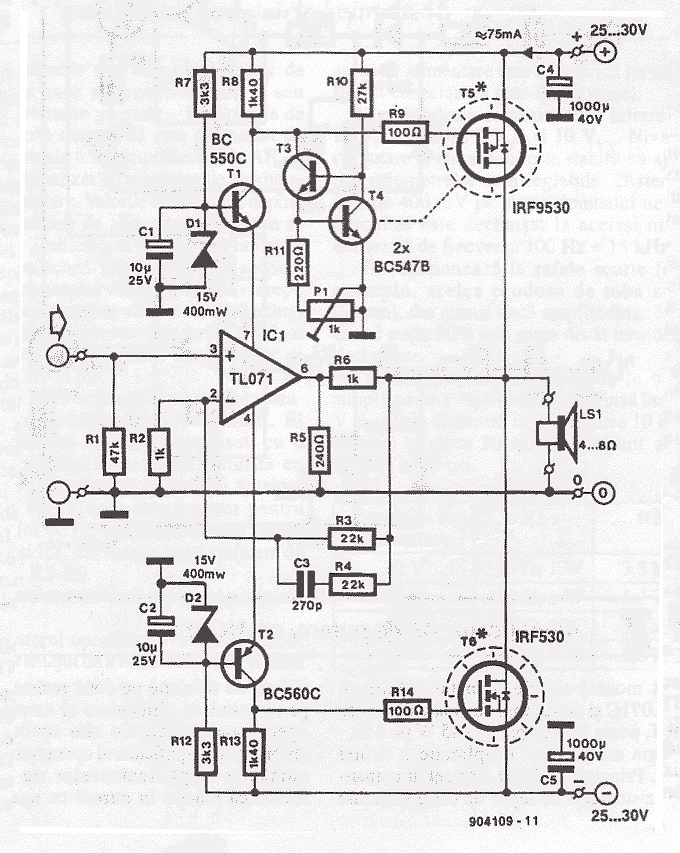
70 Watt MOSFET Audio Amplifier
This simple power MOSFET audio amplifier circuit utilizes a TL071C operational amplifier and two MOSFETs (IRF9530 and IRF530), capable of delivering up to 45 Watts to an 8-ohm speaker. The schematic is based on a Siliconix application and incorporates variations...