

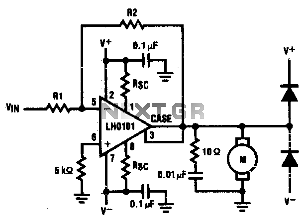

Servo motor amplifier
Motor driver amplifier will deliver the rated current into the motor. Care should be taken to keep power dissipation within the permitted level...
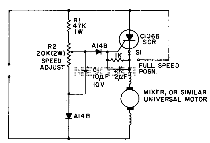
Universal-motor speed control
Simple half-wave motor speed control is effective for use with small universal (ac/dc) motors. Maximum current capability 2 amps RMS. Because speed-dependent fe...
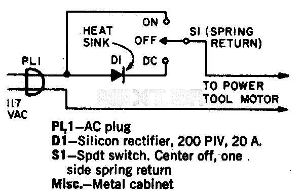
AC motor brake
A shot of direct current will instantly stop any ac power tool motor. Switch Si is a center-off, one side spring return. With Si on, ac will be fed to the motor...
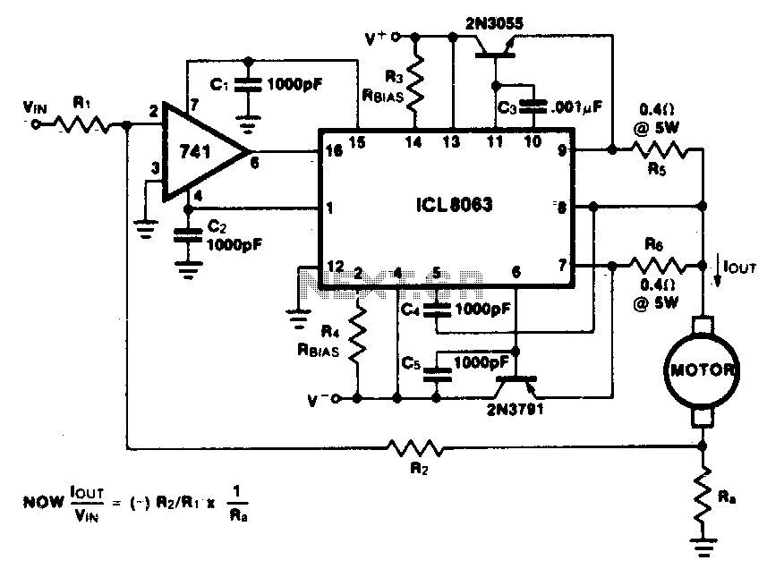
Constant current motor drive circuit
This minimum de vice circuit can be used to drive dc motors where there is some likelihood of stalling or lock up...

Motor speed control
Switching action of the 2N4990 allows smaller capacitors...
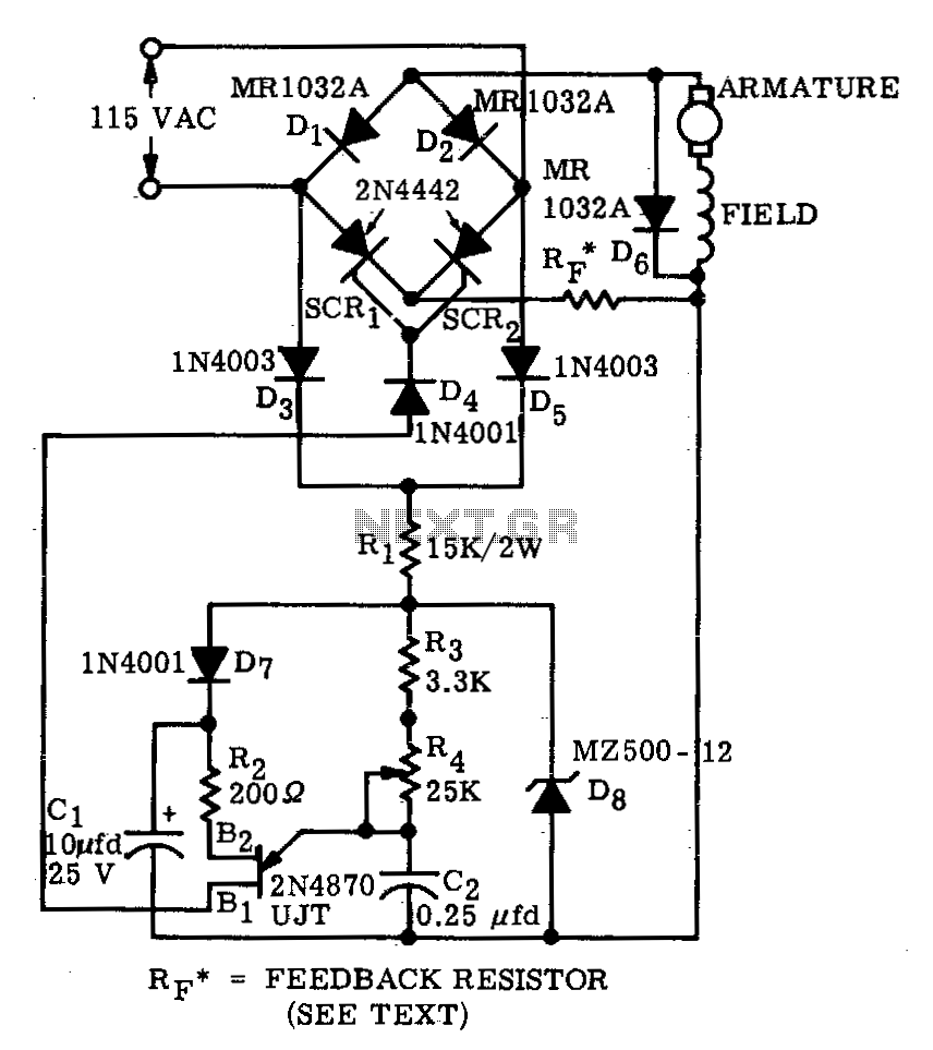
High-torque motor speed control
A bridge circuit consisting of two SCRs and two silicon rectifiers furnishes full-wave power to the motor. Diodes, D3 and D5, supply dc to the trigger circuit t...
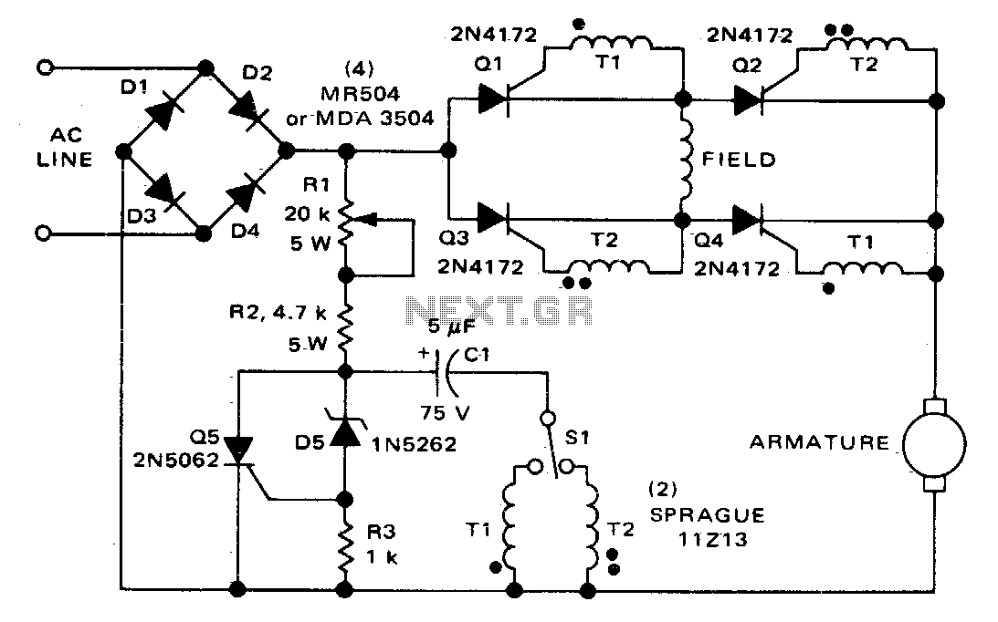
Direction and speed control for series-wound motors
The circuit shown here can be used to control the speed and direction of rotation of a series-wound dc motor. Silicon controlled rectifiers Q1-Q4, which are con...
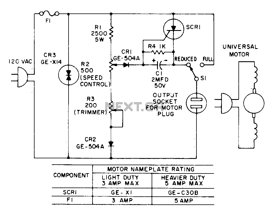
Plug-in speed control for tools or appliances
Most standard household appliances and portable hand tools can be adapted to variable -speed operation by use of this simple half-wave SCR phase control. It can...
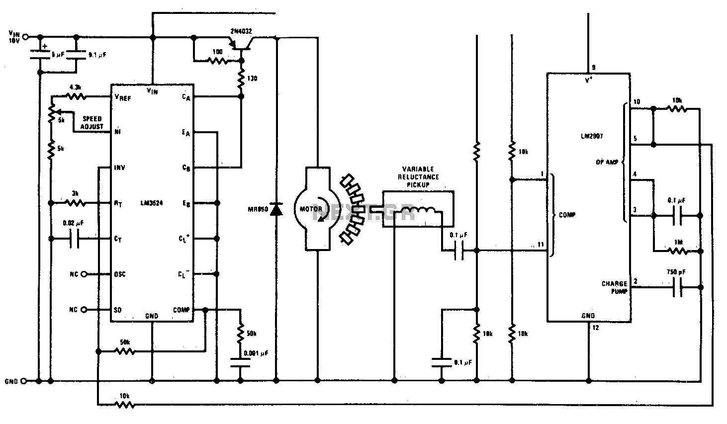
Motor speed control
This circuit is a regulating series dc motor speed control using the LM3524 for the control and drive for the motor and the LM2907 as a speed sensor...
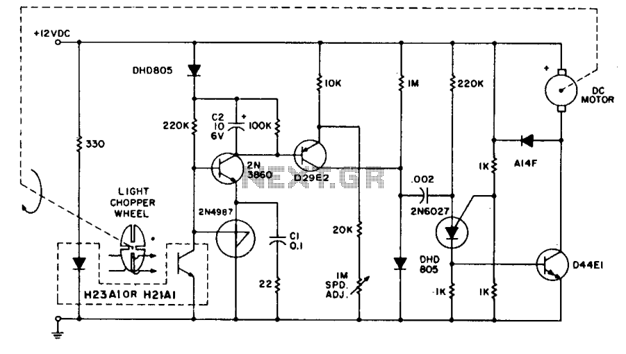
Tachometer feedback control
The system utilizes the H21A1 and a chopper disc to provide superior speed regulation when the dynamic characteristics of the motor system and the feedback syst...
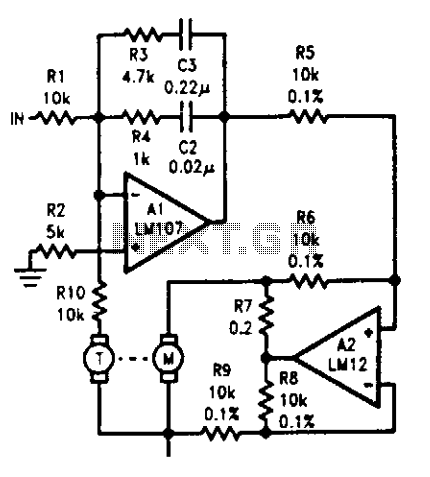
Motor-tachometer speed control
The tachometer, on the same shaft as the dc motor, is simply a generator. It gives a dc output voltage proportional to the speed of the motor. A summing amplifi...
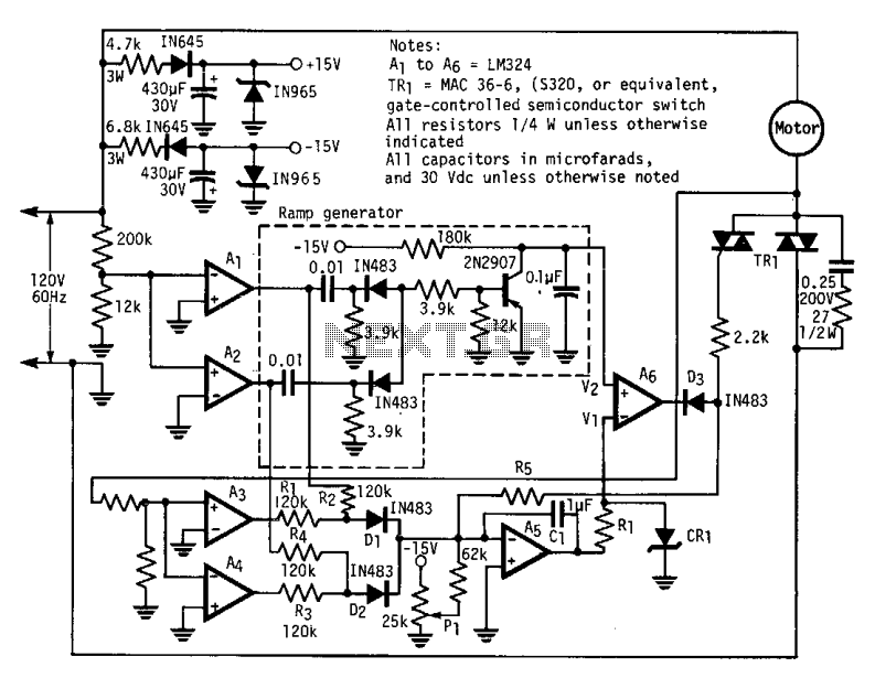
Three-phase factor controller
The modified power-factor controller, developed at the Marshall Space Flight Center, employs a phase detector for each of the three phase windings of a delta-co...
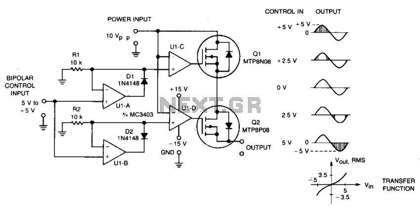
Dc servo bipolar control
This circuit accepts bipolar control inputs of ± 5 V and provides a phase-chopped output to a dc load (such as a servo motor) of the same polarity as the inp...
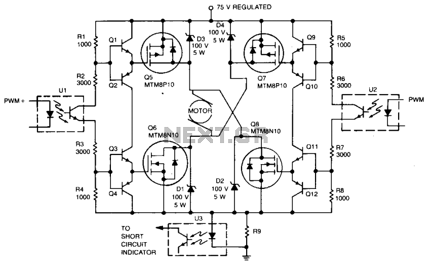
Servo motor drive amplifier
Digital ICs and opto-isolators provide the drive for this TMOS servo amplifier, resulting in fewer analog circuits and less drift. Fast and consistent turn-on a...
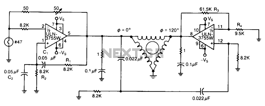
Three-phase ac motor driver 2
By varying either Rl or R2, the oscillator frequency can be adjusted over a narrow range. The R3/R4 ratio sets the second amplifier's gain to compensate for sig...
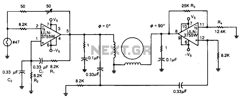
Two-phase ac motor driver
Because of its high amplification factor and built-in power-output stage, an integrated power operational amplifier makes a convenient driver for ac motors. One...
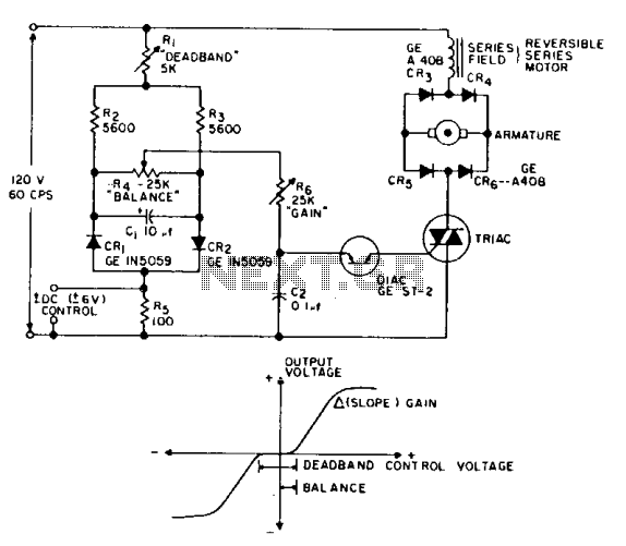
Reversing motor drive dc control
This is a positioning servo drive featuring adjustment of balance, gain, and deadband. In addition to control from a dc signal, mechanical input can be fed into...
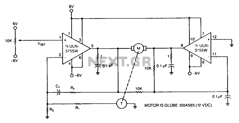
Dc motor speed control 2
Power op amps provide accurate speed control for dc motors. The circuit provides bidirectional speed control. The amplifiers' push-pull configuration ensures a ...
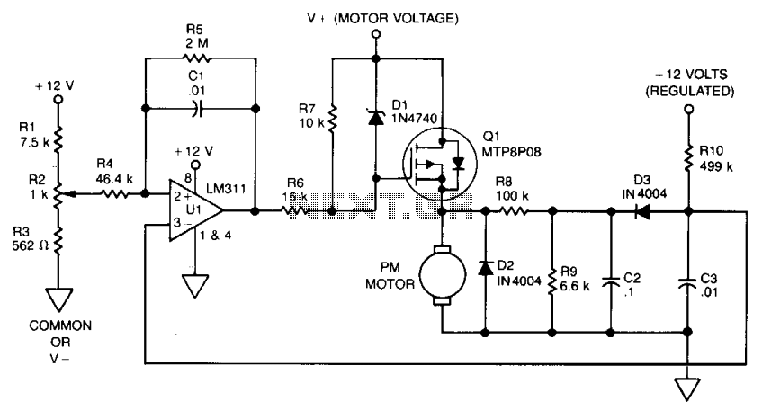
Back emf motor speed control
The use of power MOSFETs allows a direct interface between logic and motor power, which permits circuit simplicity as well as high efficiency. This speed contro...
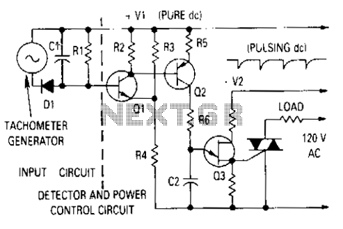
Motor control with tachometer
The ^generator output is rectified then filtered and applied between the positive supply voltage and the base of the detector transistor. This provides a negati...