


1 to 5 Video splitter
#video splitter
#operational amplifier
#EL2020
#bandwidth
#2N3866
#75-ohm impedance
#gain adjustment
#video signal
#transistor
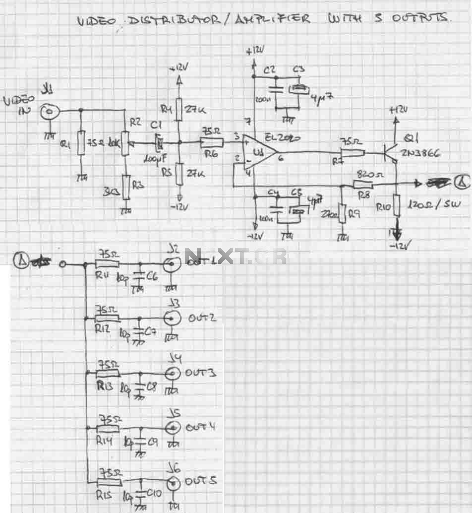
Description: The circuit is based on the type EL2020 (or similar) operational amplifier which is marked by large bandwidth. The LL2020 amplifies the video signal applied to the input stage, with a gain adjustment range of ±6 dB. Output transistor Q1, a 2N3866, applies the video signal to the five outputs designed to drive loads with 75-Ω impedance. Video fans and professionals in the field will find in this small signal distributor-amplifier an excellent ally when it’s necessary to distribute a single video signal across several equipment. The circuit shown here should have a lot of applications. Basically, the distribution amplifier takes the composite video signal from a video player (VCR) or a video generator (analog output) and buffers it in such a way that it can be simultaneously applied to up to five different video equipment inputs, like monitors, TV sets, other VCRs, and so on. For example, in a hall, the image produced by a central DVD player can be shown on five different TV screens with the sound reproduced through a separate amplifier. The circuit requires a ±12 V symmetrical supply voltage, which can be obtained from a conventional power supply as shown by the schematic.
The described circuit utilizes the EL2020 operational amplifier, known for its high bandwidth and low distortion, making it suitable for video applications. The operational amplifier is configured to amplify the composite video signal, ensuring that the signal integrity is maintained while adjusting the gain within a range of ±6 dB. This gain adjustment is crucial for matching the output levels to the requirements of various video equipment.
The output stage employs a 2N3866 transistor, which is responsible for driving the five output channels. Each output is designed to interface with video equipment that presents a 75-ohm load, which is standard for video signals to minimize reflections and ensure signal fidelity. The design of the circuit allows for simultaneous distribution of the video signal to multiple devices, which is particularly useful in scenarios where a single source needs to be displayed on multiple screens.
The circuit's operation is powered by a ±12 V symmetrical power supply, which can be easily sourced from standard power supply units. This voltage level is suitable for the operational amplifier and ensures that the circuit can handle the required signal levels without distortion.
In practical applications, this circuit can be employed in various settings, such as educational institutions, conference rooms, and entertainment venues, where multiple displays are needed to show the same content. The compact nature of the circuit makes it an efficient solution for video distribution, allowing for neat installation and reduced wiring complexity. Overall, this small signal distributor-amplifier is a valuable tool for any video professional looking to enhance their setup.The circuit is based on the type EL2020 (or similar) operational amplifier which is marled by large bandwidth. The LL2020 amplifies the video signal applied to the input stage, with a gain adjustment range of ±6 dB.
Output transistor Q1, a 2N3866, applies the video signal to the five outputs designed to drive loads with 75-? impedance. Video fans and professionals in the field will find in this small signal distributor-amplifier an excellent ally when it’s necessary to distribute a single video signal across several equipments. The circuit shown here should have a lot of applications. Basically, the distribution amplifier takes the composite video signal from a video player (VCR) or a video generator (analogue output) and buffers it in such a way that it can be simultaneously applied to up to five different video equipment inputs, like monitors, TV sets, other VCRs and so on.
For example, in a hall, the image produced by a central DVD player can be shown on five different TV screens with the sound reproduced through a separate amplifier. The circuit requires a ±12 V symmetrical supply voltage, which can be obtained from a conventional power supply as shown by the schematic.
The described circuit utilizes the EL2020 operational amplifier, known for its high bandwidth and low distortion, making it suitable for video applications. The operational amplifier is configured to amplify the composite video signal, ensuring that the signal integrity is maintained while adjusting the gain within a range of ±6 dB. This gain adjustment is crucial for matching the output levels to the requirements of various video equipment.
The output stage employs a 2N3866 transistor, which is responsible for driving the five output channels. Each output is designed to interface with video equipment that presents a 75-ohm load, which is standard for video signals to minimize reflections and ensure signal fidelity. The design of the circuit allows for simultaneous distribution of the video signal to multiple devices, which is particularly useful in scenarios where a single source needs to be displayed on multiple screens.
The circuit's operation is powered by a ±12 V symmetrical power supply, which can be easily sourced from standard power supply units. This voltage level is suitable for the operational amplifier and ensures that the circuit can handle the required signal levels without distortion.
In practical applications, this circuit can be employed in various settings, such as educational institutions, conference rooms, and entertainment venues, where multiple displays are needed to show the same content. The compact nature of the circuit makes it an efficient solution for video distribution, allowing for neat installation and reduced wiring complexity. Overall, this small signal distributor-amplifier is a valuable tool for any video professional looking to enhance their setup.The circuit is based on the type EL2020 (or similar) operational amplifier which is marled by large bandwidth. The LL2020 amplifies the video signal applied to the input stage, with a gain adjustment range of ±6 dB.
Output transistor Q1, a 2N3866, applies the video signal to the five outputs designed to drive loads with 75-? impedance. Video fans and professionals in the field will find in this small signal distributor-amplifier an excellent ally when it’s necessary to distribute a single video signal across several equipments. The circuit shown here should have a lot of applications. Basically, the distribution amplifier takes the composite video signal from a video player (VCR) or a video generator (analogue output) and buffers it in such a way that it can be simultaneously applied to up to five different video equipment inputs, like monitors, TV sets, other VCRs and so on.
For example, in a hall, the image produced by a central DVD player can be shown on five different TV screens with the sound reproduced through a separate amplifier. The circuit requires a ±12 V symmetrical supply voltage, which can be obtained from a conventional power supply as shown by the schematic.
TRANSISTORIZED AM RADIO
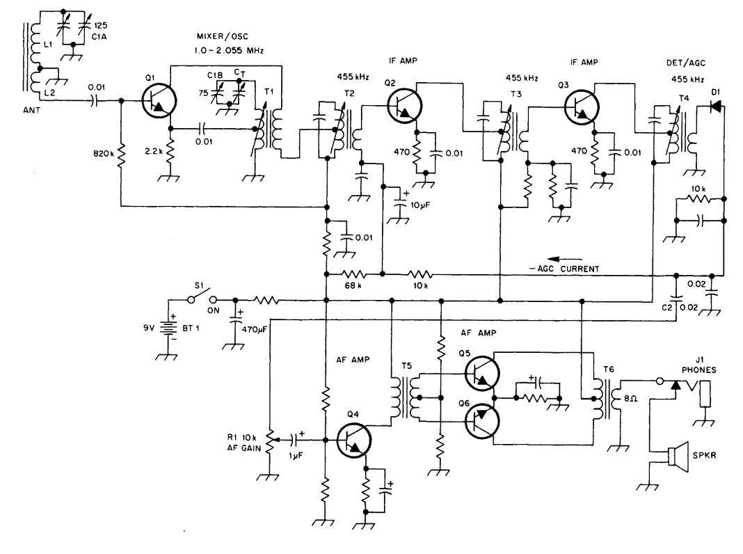
The schematic illustrates a standard AM radio circuit utilizing NPN transistors. This generic circuit does not provide specific values for all components, serving instead as a reference point for experimenters to begin their projects.
The schematic of a typical transistor AM...
Flasher Circuits
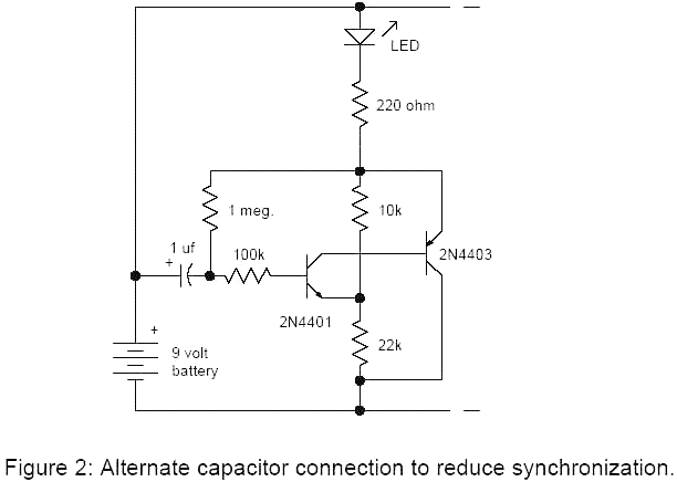
The basic two-transistor flasher has become widely utilized in various applications due to its simplicity and versatility. It has been employed in circuits such as a micropower low battery indicator, a lightning detector, an off-line switching power supply, a micropower...
TA-1500 fever amplifier circuit
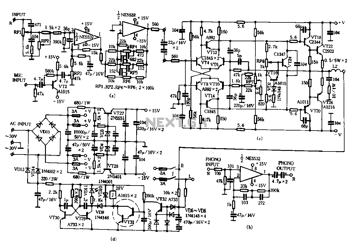
Only the R channel is shown, with the original reference PCB label. Figure (a) illustrates the front tone circuit, which consists of a common negative feedback operational amplifier in an RC circuit configuration. The microphone signal is amplified by VTz,...
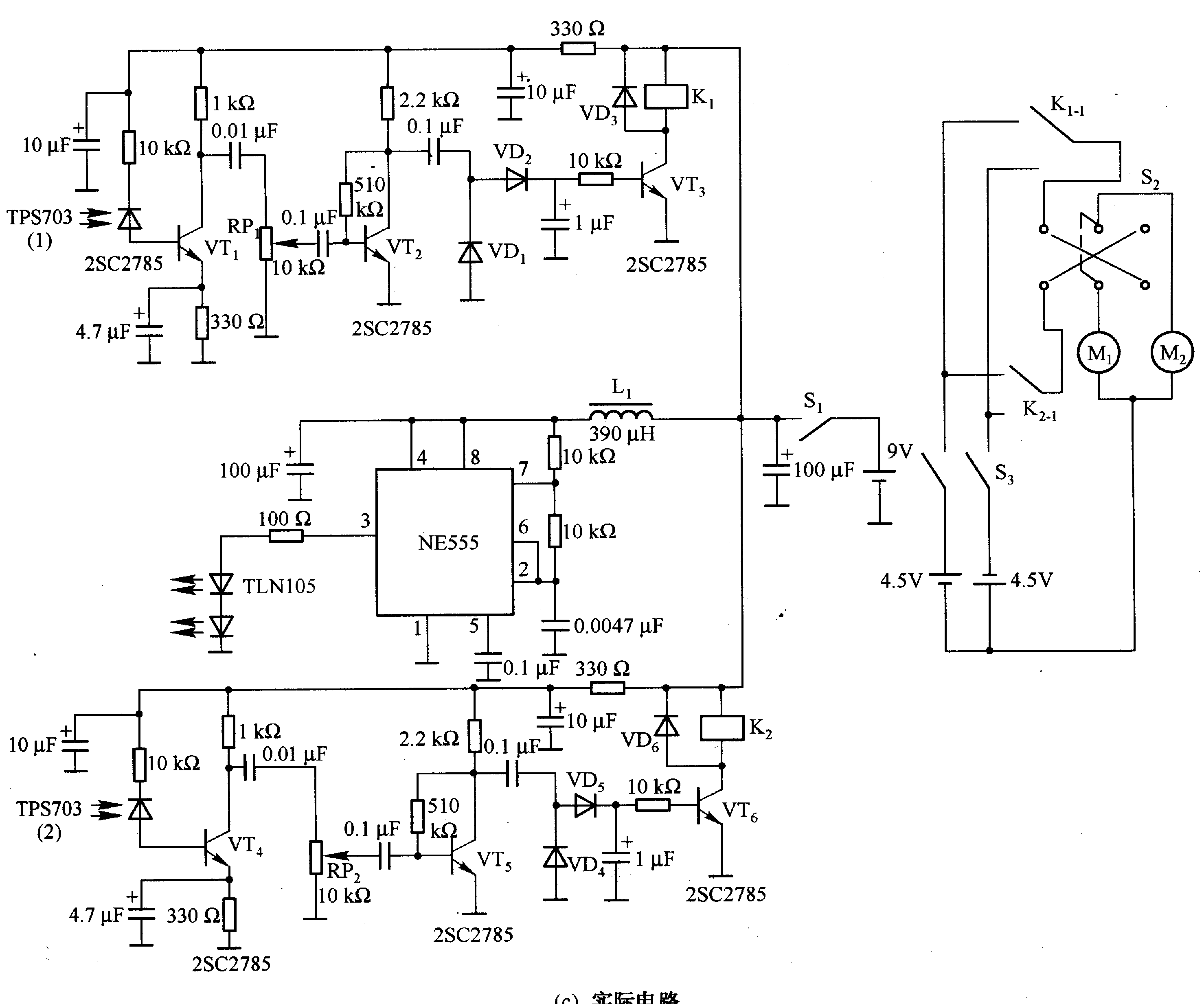
Robot control circuit composed of transistor and NE555
Figure 2-33 (a) illustrates the schematic diagram of a robot approaching an object. When no objects are detected in front of the robot, it moves forward in a straight line. If an object is detected on the left or right...
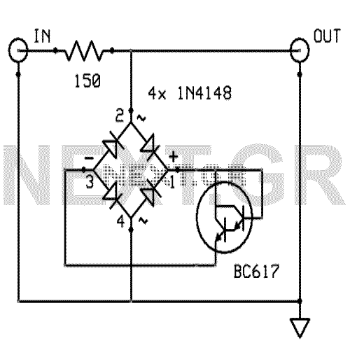
Amplifier input signal overdrive auto-protection
That circuit protects the overdriven signals going into an amplifier. Instead of a zener diode, we use a transistor. That way we ensure that the above the ordinary input voltages (1 volt r.m.s.) can be achieved without distortion. Also, the...

Transistor Amplifier Circuit with Diagram for 12 Watts
A simple transistor amplifier circuit diagram and schematic that can be used as a 12-watt audio transistor amplifier. An operational amplifier (op-amp) integrated circuit (IC) is used to produce the required gain.
This circuit is designed to amplify audio signals, making...
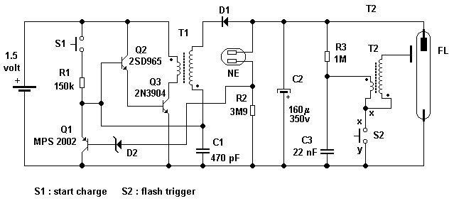
Camera flash circuit
A simple transistor generator and transformer converts a 1.5V battery voltage to several hundred volts. This high voltage current then passes through a diode, which rectifies the current to DC. This DC current is stored in a relatively large capacitor....
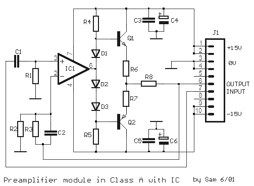
Class A Modular Preamplifier with Single Integrated Circuit
The circuit is based on a single operational amplifier integrated circuit designed to produce a modular preamplifier that operates in Class A configuration.
The modular preamplifier circuit utilizes a single operational amplifier (op-amp) integrated circuit, which serves as the primary amplification...
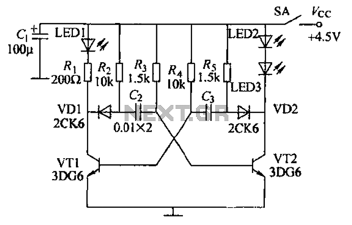
Multivibrator infrared transmitter circuit
Transistors VT1, VT2, and associated RC components are configured to form a multivibrator. The multivibrator operates with resistors Ra and R4 serving as base bias resistors for VT2 and VT1, respectively. When the switch SA is closed after applying power...