


15V-chopper-amplifier
#inverting amplifier
#gain
#signal amplification
#MAX420
#submillivolt signals
#operational amplifier
#circuit design
#electronics
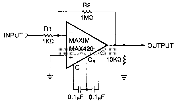
Description: This circuit is a gain-of-1000 inverting amplifier designed to amplify submillivolt signals to levels suitable for further processing. In most system applications, utilizing maximum gain in the MAX420 is advantageous, as it minimizes the effects of offsets in later stages. For instance, if the circuitry following the MAX420 has an offset of 5 mV, the additional offset referred back to the MAX420 input (with a gain of 1000) will result in an offset of 5 µV, effectively doubling the system's offset error.
The described circuit employs the MAX420 operational amplifier configured as an inverting amplifier, which is characterized by its high gain and low noise performance. The gain of 1000 indicates that the input signal will be amplified 1000 times, making it suitable for processing very low-level signals. The inverting configuration is particularly useful in applications where signal inversion is not a concern, and it provides a straightforward method for achieving high gain.
The circuit typically consists of a feedback resistor (Rf) and an input resistor (Rin). The gain (Av) of the inverting amplifier can be calculated using the formula Av = -Rf/Rin. To achieve a gain of 1000, the values of Rf and Rin must be selected accordingly. For example, if Rin is set to 1 kΩ, Rf would need to be set to 1 MΩ to achieve the desired gain.
In practical applications, it is crucial to consider the bandwidth and slew rate of the MAX420, as these parameters will affect the amplifier's performance at high frequencies. Proper decoupling capacitors should also be used near the power supply pins of the MAX420 to minimize noise and ensure stable operation. Additionally, careful layout and grounding practices are essential to reduce parasitic capacitance and inductance, which can introduce unwanted noise and distort the amplified signal.
The circuit's design should also account for the input and output impedance, ensuring that the amplifier can interface effectively with subsequent stages of the signal processing chain. By maximizing the gain in the MAX420, the impact of any offsets introduced by following circuitry is significantly reduced, thereby enhancing overall system accuracy and reliability.This simple circuit is a gain-of-1000 inverting amplifier. It will amplify submillivolt signals up to signal levels suitable for further processing. In almost all system applications, it is best to use as OUTPUT much gain as possible in the MAX420, thus minimizing the effects of later-stage offsets. For example, if circuitry following the MAX420 has an offset of 5 m V, the additional offset referred back to the MAX420 input (gain = 1000) will be 5 p.V, doubling Fig. 3-4 the system"s offset error.
The described circuit employs the MAX420 operational amplifier configured as an inverting amplifier, which is characterized by its high gain and low noise performance. The gain of 1000 indicates that the input signal will be amplified 1000 times, making it suitable for processing very low-level signals. The inverting configuration is particularly useful in applications where signal inversion is not a concern, and it provides a straightforward method for achieving high gain.
The circuit typically consists of a feedback resistor (Rf) and an input resistor (Rin). The gain (Av) of the inverting amplifier can be calculated using the formula Av = -Rf/Rin. To achieve a gain of 1000, the values of Rf and Rin must be selected accordingly. For example, if Rin is set to 1 kΩ, Rf would need to be set to 1 MΩ to achieve the desired gain.
In practical applications, it is crucial to consider the bandwidth and slew rate of the MAX420, as these parameters will affect the amplifier's performance at high frequencies. Proper decoupling capacitors should also be used near the power supply pins of the MAX420 to minimize noise and ensure stable operation. Additionally, careful layout and grounding practices are essential to reduce parasitic capacitance and inductance, which can introduce unwanted noise and distort the amplified signal.
The circuit's design should also account for the input and output impedance, ensuring that the amplifier can interface effectively with subsequent stages of the signal processing chain. By maximizing the gain in the MAX420, the impact of any offsets introduced by following circuitry is significantly reduced, thereby enhancing overall system accuracy and reliability.This simple circuit is a gain-of-1000 inverting amplifier. It will amplify submillivolt signals up to signal levels suitable for further processing. In almost all system applications, it is best to use as OUTPUT much gain as possible in the MAX420, thus minimizing the effects of later-stage offsets. For example, if circuitry following the MAX420 has an offset of 5 m V, the additional offset referred back to the MAX420 input (gain = 1000) will be 5 p.V, doubling Fig. 3-4 the system"s offset error.
Electronics Projects Circuits
Over 1400 top electronics projects and electronic circuits with photos, datasheets, and easy-to-read schematics, along with explanations of how they work and how to build them.
The collection comprises a vast array of electronics projects suitable for enthusiasts and professionals alike....
Square transform circuit diagram
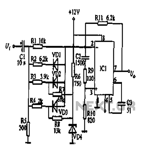
At the input of the operational amplifier, a resistor-diode network can be constructed to create a square-law function conversion circuit. This resistor-diode network acts as a voltage divider, where the input voltage variations lead to different partial pressures. The three...
X10 operational amplifier
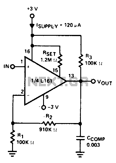
The amplifier is 3 dB down at 100 kHz and has a slew rate of 0.02 V/µs.
The amplifier's performance characteristics indicate that it experiences a 3 dB attenuation at a frequency of 100 kHz. This specification suggests that at this...
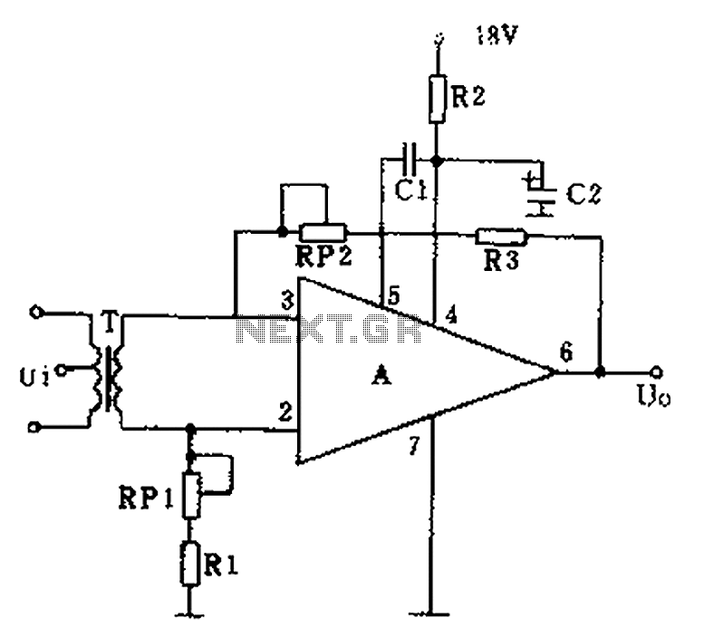
GF2A op amp audio amplifier circuit diagram
The operational amplifier A is utilized in an audio preamplifier circuit. Its advantages include compact size, low noise, low power consumption, and excellent consistency. The operational amplifier can achieve significant negative feedback while increasing output without distortion. The signal distortion...
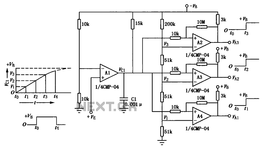
Delay circuit of a multi-level output
A multi-stage delay circuit is presented in this schematic. The operational amplifiers are configured as comparators. Operational amplifier A1 operates when the voltage at the inverting input exceeds + VE. As the voltage at the inverting input of operational amplifiers...
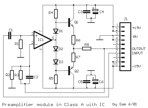
Class A Modular Preamplifier with Single Integrated Circuit
The circuit is based on a single operational amplifier integrated circuit designed to produce a modular preamplifier that operates in Class A configuration.
The modular preamplifier circuit utilizes a single operational amplifier (op-amp) integrated circuit, which serves as the primary amplification...
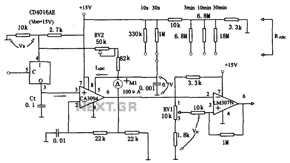
Long timed circuit diagram LM307N CA3094
The long timer circuit utilizes an operational amplifier, specifically the CA3094, to control the discharge formula for extended timing. This is typically achieved by adjusting the variable resistor RV1, which alters the timing duration to meet specific requirements.
The long timer...
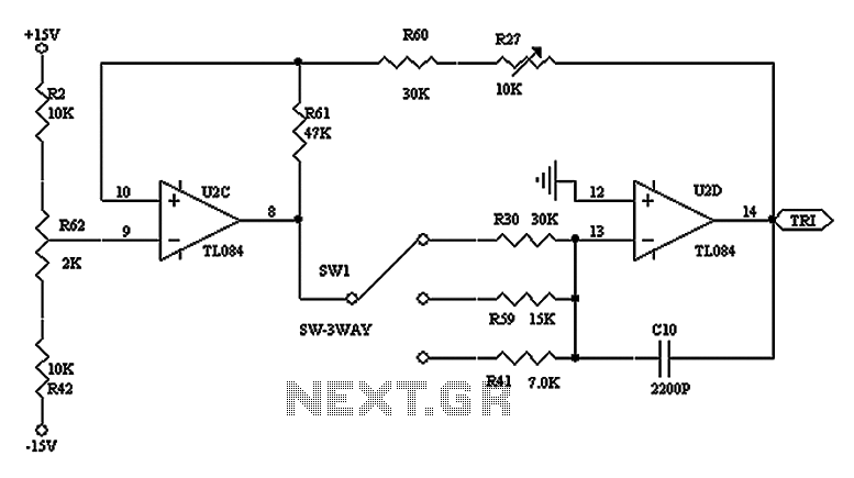
The triangular wave carrier generator circuit diagram
The triangular wave circuit consists of two operational amplifiers (OPs). R62 serves as the offset adjustment, while R27 is utilized for peak adjustment. A switch is included to select different resistances, allowing for the generation of triangular waves at varying...
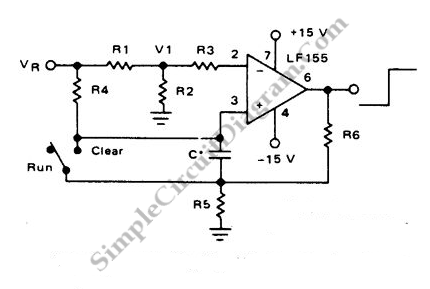
Long Interval RC Timer Using Op-Amp
By utilizing a high-gain, high-impedance operational amplifier, it is possible to construct a long time delay circuit using a resistor-capacitor (RC) configuration, as it allows for high...
An operational amplifier (op-amp) is a versatile component widely used in electronic circuits, particularly...