


Active bandpass filter principle
#bandpass filter
#active filter
#quality factor
#center frequency
#second order filter
#signal processing
#filter design
#operational amplifier circuit
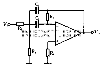
Description: The performance of a second-order band-pass filter is primarily influenced by the quality factor (Q) and the center frequency (Si). To adjust the Q value, R3 should be modified first, followed by adjustments to C0. However, these adjustments will also affect R3 and Si. Figure R4 illustrates that Si is independent, allowing for the capacitor C to be opened. According to the principles of equality, the DC resistance at the inverting terminal of the operational amplifier should be grounded, leading to R4 being equal to R3. The maximum Q value for a second-order band-pass filter should not exceed 20, with a general recommendation of around 10. Selecting a higher Q value results in a lower resistance of 2 ohms, which can severely attenuate the input signal and increase the burden on the amplifier. The Q value is sensitive to the number of parameter element errors, with a general recommendation of approximately 10. The maximum transmission ratio (KF) can vary from 1 to 100, and for display driver stage amplifiers with adjustable gain, a KF value of around 10 is advisable. Once the values of Q, fo, and KF are determined, the component values for R1, R3, C, and R4 can be calculated for the filter.
The second-order band-pass filter is a critical component in various electronic applications, particularly in signal processing where specific frequency ranges need to be isolated. The design of this filter centers around the quality factor (Q), which defines the filter's selectivity and bandwidth. A higher Q value indicates a narrower bandwidth and greater selectivity, but it also poses challenges such as increased sensitivity to component tolerances and potential signal attenuation.
In practical implementations, the adjustment of R3 affects the Q factor directly. Increasing R3 raises the Q value, enhancing selectivity but also risking excessive attenuation of the input signal. Conversely, reducing R3 lowers the Q factor, broadening the bandwidth and potentially allowing more of the input signal to pass through. The capacitor C0 also plays a pivotal role in determining the filter's center frequency (Si) and must be adjusted in conjunction with R3 to maintain the desired performance characteristics.
The theoretical foundation of the filter's operation can be illustrated using an operational amplifier (op-amp) configuration. The inverting terminal's DC resistance, when grounded, establishes a feedback loop that stabilizes the filter's response. The relationship between R3 and R4 is crucial, as they must be matched to ensure optimal performance. The design suggests that for effective operation, R4 should equal R3, creating a balanced circuit that adheres to the principles of equality in feedback networks.
The maximum allowable Q value of 20 should be approached cautiously, as exceeding this threshold can lead to undesirable effects such as increased noise and distortion. The recommendation of a Q value around 10 strikes a balance between selectivity and stability, making it suitable for most applications. Additionally, the maximum transmission ratio (KF) should be carefully selected based on the specific requirements of the application, with a value around 10 being optimal for amplifiers with adjustable gain.
To finalize the design, the values of R1, R3, C, and R4 need to be calculated based on the desired Q, center frequency (fo), and transmission ratio (KF). This ensures that the second-order band-pass filter meets the necessary specifications for its intended application, providing reliable and effective signal processing capabilities.Second order band-pass filter performance depends primarily on the quality factor Q and center frequency Si. In order to adjust the Q and. t a general first adjust R3 to change the Q value, and then adjust to change C 0. But the adjustment will affect R3 Si. Figure R4 and Si-independent, so that the capacitor C is now open, according to the same phase-inverting terminal of the operational amplifier to ground the DC resistance of the principles of equality, availability R4 = R3 = R3. Second order bandpass filter the Q value of the maximum undeclared more than 20, and generally 10 is appropriate, Q values of the election was high, resistance is 2 feet lower bound value, so the input signal will be severely attenuated, and to increase the amplifier burden.
Since the Q value of the parameter element number of errors is very sensitive in general to 0 10 appropriate. KF is the maximum transmission ratio can range from 1 ^ f100 select within, if the display driver stage amplifier with an adjustable gain, the band-pass filter 10 to take appropriate din KF.
In determining the value of Q, fo KF and after, can be obtained in the filter R l, R R 3, C and R4 of value.
The second-order band-pass filter is a critical component in various electronic applications, particularly in signal processing where specific frequency ranges need to be isolated. The design of this filter centers around the quality factor (Q), which defines the filter's selectivity and bandwidth. A higher Q value indicates a narrower bandwidth and greater selectivity, but it also poses challenges such as increased sensitivity to component tolerances and potential signal attenuation.
In practical implementations, the adjustment of R3 affects the Q factor directly. Increasing R3 raises the Q value, enhancing selectivity but also risking excessive attenuation of the input signal. Conversely, reducing R3 lowers the Q factor, broadening the bandwidth and potentially allowing more of the input signal to pass through. The capacitor C0 also plays a pivotal role in determining the filter's center frequency (Si) and must be adjusted in conjunction with R3 to maintain the desired performance characteristics.
The theoretical foundation of the filter's operation can be illustrated using an operational amplifier (op-amp) configuration. The inverting terminal's DC resistance, when grounded, establishes a feedback loop that stabilizes the filter's response. The relationship between R3 and R4 is crucial, as they must be matched to ensure optimal performance. The design suggests that for effective operation, R4 should equal R3, creating a balanced circuit that adheres to the principles of equality in feedback networks.
The maximum allowable Q value of 20 should be approached cautiously, as exceeding this threshold can lead to undesirable effects such as increased noise and distortion. The recommendation of a Q value around 10 strikes a balance between selectivity and stability, making it suitable for most applications. Additionally, the maximum transmission ratio (KF) should be carefully selected based on the specific requirements of the application, with a value around 10 being optimal for amplifiers with adjustable gain.
To finalize the design, the values of R1, R3, C, and R4 need to be calculated based on the desired Q, center frequency (fo), and transmission ratio (KF). This ensures that the second-order band-pass filter meets the necessary specifications for its intended application, providing reliable and effective signal processing capabilities.Second order band-pass filter performance depends primarily on the quality factor Q and center frequency Si. In order to adjust the Q and. t a general first adjust R3 to change the Q value, and then adjust to change C 0. But the adjustment will affect R3 Si. Figure R4 and Si-independent, so that the capacitor C is now open, according to the same phase-inverting terminal of the operational amplifier to ground the DC resistance of the principles of equality, availability R4 = R3 = R3. Second order bandpass filter the Q value of the maximum undeclared more than 20, and generally 10 is appropriate, Q values of the election was high, resistance is 2 feet lower bound value, so the input signal will be severely attenuated, and to increase the amplifier burden.
Since the Q value of the parameter element number of errors is very sensitive in general to 0 10 appropriate. KF is the maximum transmission ratio can range from 1 ^ f100 select within, if the display driver stage amplifier with an adjustable gain, the band-pass filter 10 to take appropriate din KF.
In determining the value of Q, fo KF and after, can be obtained in the filter R l, R R 3, C and R4 of value.
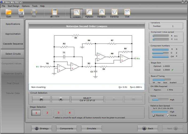
Filter Wiz PRO
Filter Wiz PRO active filter designer version 4 has just been released. Version 4 represents a major advance in the rapid design of stable and effective active filters. More: completely new interface - allows instant access to all completed phases...
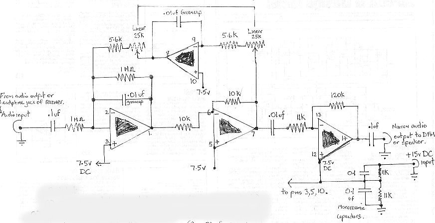
audio bandpass filter
The audio bandpass filter described is beneficial for amplifying and filtering weak AM TV video carriers. For instance, a digital frequency audio multimeter (DFM) may lack sufficient input sensitivity for measuring extremely weak single sideband (SSB) TV video audio signals....
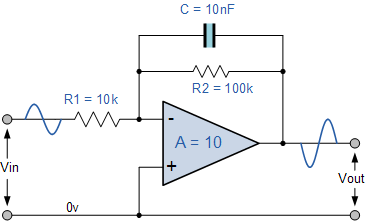
The Active Low Pass Filter
Electronics tutorial about active low pass filters, including low pass filter frequency response, op-amp voltage gain, and active filter construction.
An active low pass filter (ALPF) is an essential component in electronics, designed to allow low-frequency signals to pass while attenuating...
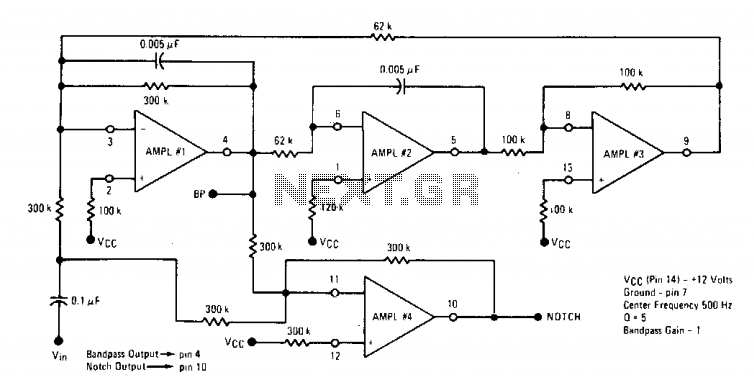
Bandpass and notch filter
The Quad op-amp MC4301 is employed to configure a filter that eliminates a specific frequency, outputting the notched frequency at the BP terminal. This is particularly useful in communication or measurement setups. By selecting appropriate components, filters capable of targeting...
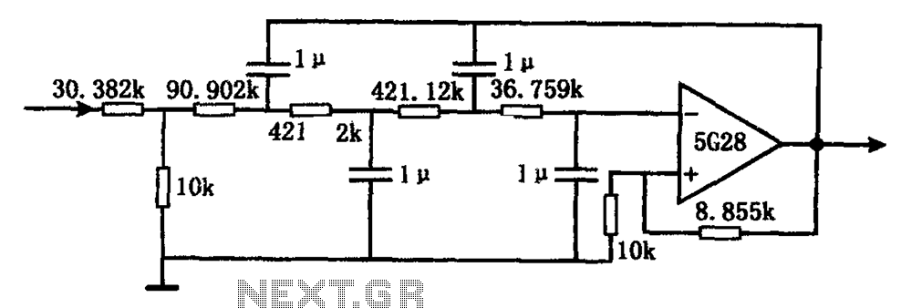
Very low frequency active filter 5G28 schematic
The circuit illustrated in the figure represents a staggered low-frequency active filter. This is a fourth-order Butterworth low-pass active filter designed to filter very low frequency (VLF) random pulse noise voltage at the DC level. The cut-off frequency is approximately...
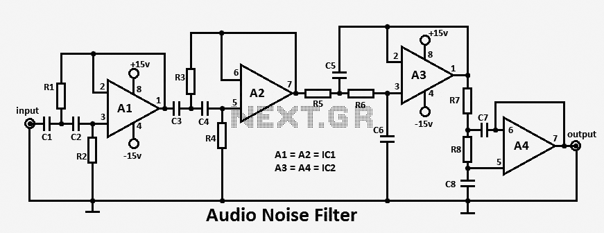
Audio Noise Filter circuit
This audio noise filter circuit functions as a bandpass filter specifically designed for the audio frequency range. It effectively filters out unwanted signals that fall below or above the desired audio frequencies. The circuit comprises two filters: a low-pass filter...
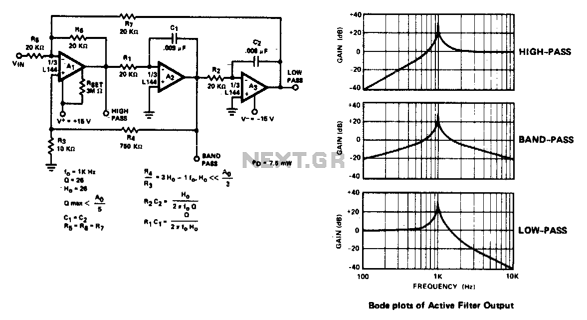
Three amplifier active filter
The active filter is a state variable filter with bandpass, high-pass, and low-pass outputs. It is a classical analog computer method of implementing a filter using three amplifiers and only two capacitors.
The state variable filter is a versatile circuit design...
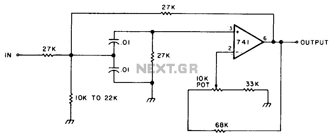
Variable bandwidth bandpass active filter
This circuit features adjustable bandwidth with a center frequency of approximately 800 Hz. A 10 kΩ potentiometer is used to adjust the bandwidth, varying from approximately ±350 Hz to ±140 Hz at the 3 dB down points.
The circuit operates around...
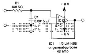
Simple Low-Pass (Lp) Active Filter For 1Khz Circuit
This simple filter utilizes an RC section as the filter element, incorporating a voltage follower to manage other frequencies. The -3 dB point is calculated as 1/(6.28 * RXCV), resulting in a response that drops 6 dB per octave above...