


Analog multiplier
#analog multiplier
#frequency-to-voltage
#voltage-to-frequency
#LTCLG43
#signal processing
#op-amp
#analog circuits
#multiplier
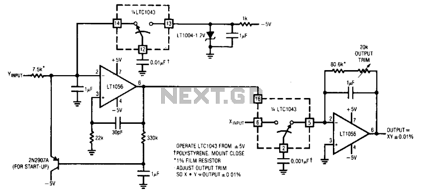
Description: The F-V input frequency is locked to the V-F output because the LTCIG43's clock is common to both sections. The F-V's reference is used as one input of the multiplier, while the V-F provides the other. To calibrate, short the X and Y inputs to 1.7320 V and trim for a 3-V output.
The described circuit utilizes a frequency-to-voltage (F-V) converter and a voltage-to-frequency (V-F) converter, both of which are synchronized by a shared clock signal generated by the LTCIG43. This synchronization ensures that the output frequency of the F-V converter directly corresponds to the input voltage level, while the V-F converter translates this frequency back into a voltage level.
In practical applications, this configuration is essential for systems requiring precise frequency measurement and control, such as in digital signal processing or communication systems. The F-V converter takes an input frequency and converts it into a proportional voltage, which is then fed into the multiplier. The output of the multiplier is influenced by the voltage from the V-F converter, which serves to maintain the stability and accuracy of the system.
Calibration of the circuit is a critical step to ensure precision in operation. By shorting the X and Y inputs to a specific reference voltage of 1.7320 V, the circuit can be fine-tuned. This adjustment is made to achieve a precise output of 3 V, which may represent a standard reference level for subsequent processing stages. The calibration process may involve using a variable resistor or potentiometer to adjust the gain of the multiplier, ensuring that the output remains consistent under varying input conditions.
Overall, this circuit configuration is a robust solution for applications requiring accurate frequency-to-voltage and voltage-to-frequency conversions, with the calibration process allowing for fine-tuning to meet specific operational requirements.The F — V input frequency is locked to the V — F output because the LTClG43's clock is common to both sections. The F — V's reference is used as one input of the multiplier, while the V — F furnishes the other.
To calibrate, short the X and Y inputs to 1.7320 V and trim for a 3-V output.
The described circuit utilizes a frequency-to-voltage (F-V) converter and a voltage-to-frequency (V-F) converter, both of which are synchronized by a shared clock signal generated by the LTCIG43. This synchronization ensures that the output frequency of the F-V converter directly corresponds to the input voltage level, while the V-F converter translates this frequency back into a voltage level.
In practical applications, this configuration is essential for systems requiring precise frequency measurement and control, such as in digital signal processing or communication systems. The F-V converter takes an input frequency and converts it into a proportional voltage, which is then fed into the multiplier. The output of the multiplier is influenced by the voltage from the V-F converter, which serves to maintain the stability and accuracy of the system.
Calibration of the circuit is a critical step to ensure precision in operation. By shorting the X and Y inputs to a specific reference voltage of 1.7320 V, the circuit can be fine-tuned. This adjustment is made to achieve a precise output of 3 V, which may represent a standard reference level for subsequent processing stages. The calibration process may involve using a variable resistor or potentiometer to adjust the gain of the multiplier, ensuring that the output remains consistent under varying input conditions.
Overall, this circuit configuration is a robust solution for applications requiring accurate frequency-to-voltage and voltage-to-frequency conversions, with the calibration process allowing for fine-tuning to meet specific operational requirements.The F — V input frequency is locked to the V — F output because the LTClG43's clock is common to both sections. The F — V's reference is used as one input of the multiplier, while the V — F furnishes the other.
To calibrate, short the X and Y inputs to 1.7320 V and trim for a 3-V output.
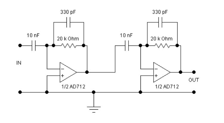
More op-amp circuits
The circuits examined thus far rely on linear feedback for their operation. The magnitude of the signal returned to the negative input is always strictly proportional to the output voltage. Consequently, within the limits defined by the operational amplifier (op-amp),...
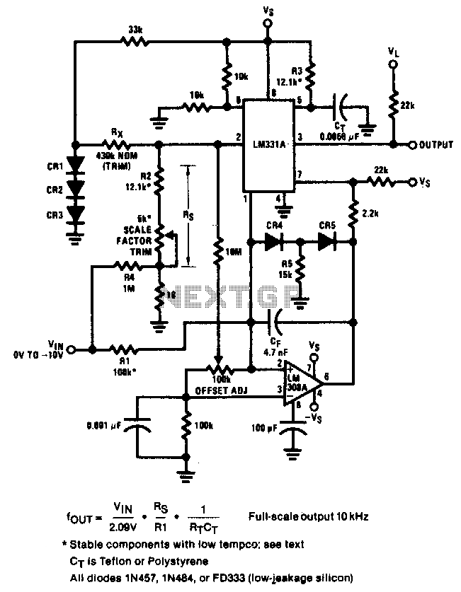
Ultra-precision v-f converter
The circuit achieves an error of better than 0.02% and a nonlinearity of 0.003% within a ±20°C range around room temperature.
The circuit's design focuses on precision and linearity, making it suitable for applications that require high accuracy in temperature measurement...
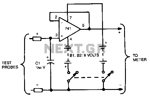
Voltage-freezer
This circuit reads and stores voltages, thereby freezing the meter reading even after the probes are removed. The operational amplifier (op-amp) is configured as a unity-gain voltage follower, with capacitor C1 located at the input to store the voltage. For...
Automatic mooring light
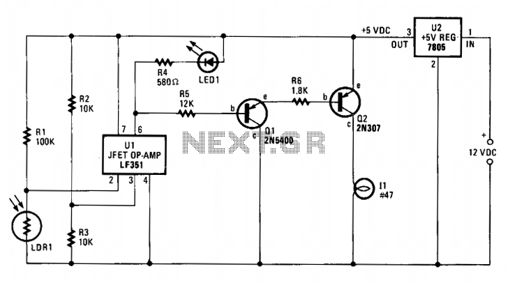
The integrated circuit U1, which can be an LF351 or a 741 operational amplifier, functions as a comparator to regulate lighting. Resistors R2 and R3 establish a reference voltage of approximately 2.5 volts at pin 3 of U1. When light...
Open-Loop Peak Detector Circuit
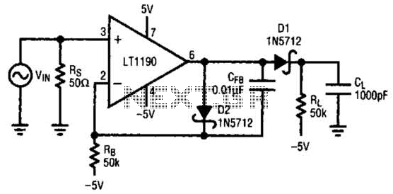
In this open-loop design, the detector diode is D1, and a level-shifting or compensating diode is D2. Load resistor RL is connected to -5 V, and an identical bias resistor RB is used to bias the compensating diode, also connected...
All-analog automatic night light circuit
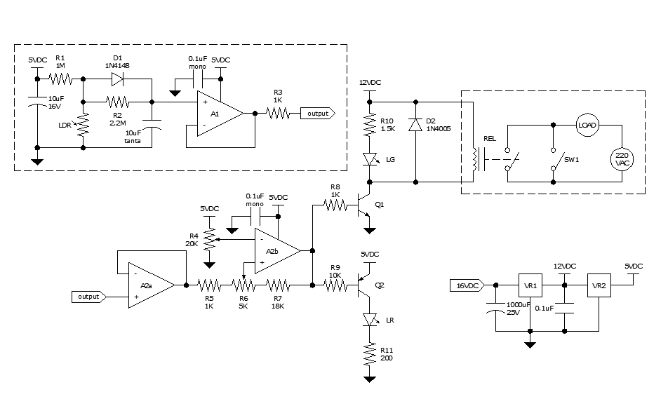
Approximately ten days ago, an all-linear automatic night light circuit was installed to control the lights in the living room. The circuit comprises three operational amplifiers (op-amps): two configured as voltage followers and one as a comparator. As depicted in...
1Mhz-voltage-to-frequency-converter
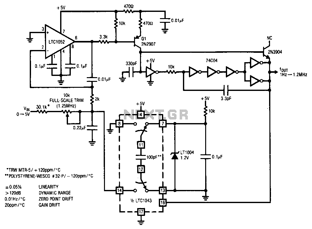
This stabilized voltage-to-frequency converter operates within a range of 1 Hz to 1.25 MHz, featuring a linearity of 0.05% and a typical temperature coefficient of 20 ppm/°C. The circuit is powered by a single 5-V supply. It employs a charge...
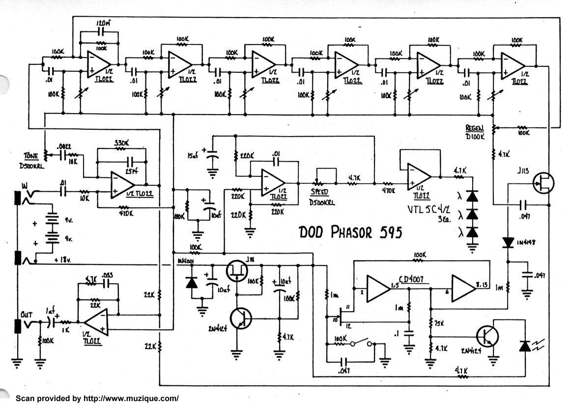
DOD Phasor 595
Protection against reverse voltage is implemented. A 10µF capacitor provides additional DC filtering. The CD4007 is configured as a flip-flop controlled by a foot switch. The output of the flip-flop drives the indicator. An 18V supply passes through a 100kΩ...
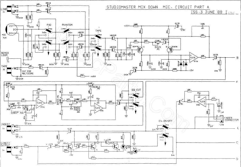
standard operational amplifier op amp circuits
This scan is from an old ETI Circuits #2 publication from the 1970s. It contains valuable operational amplifier information that is highly useful. With some knowledge, the six circuits presented serve as an instant reference, enabling various applications. These circuits...