


BiQuad Filter Circuit Diagram using LM3403 Quad Op Amp
#LM3403
#quad op amp
#BiQuad filter
#high gain
#frequency compensation
#dual power supply
#single power supply
#filter circuit
#audio processing
#signal filtering
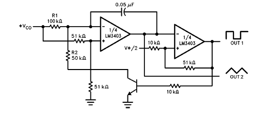
Description: The LM3403 op-amp family includes the LM3303, which is a monolithic quad op-amp known for its high gain. It features a compensated internal frequency, allowing it to operate effectively across a wide range of voltages from both single and dual power supplies. The provided circuit diagram illustrates a biquad filter utilizing the LM3403 quad op-amp. The design operates at a center frequency of 1000 Hz, with a bandwidth of 100 W, a center frequency gain (TBP) of 1, and a bandpass notch gain (TN) of 1. The resistor values are R = 160 kOhm, R1, R2, and R3 are 1.6 MOhm, and the capacitor value is C = 0.001 µF. The quality factor (Q) is calculated as BW/fo, where fo = 1/(2πRC). The reference voltage (VREF) is set to 0.5 * Vcc, R1 is determined as Q * R, R2 as R1/TBP, R3 as TN * R2, and C1 is equal to 10 * C.
The LM3403 op-amp family, particularly the LM3303 model, is designed for applications requiring high precision and stability. The monolithic structure contributes to reduced noise and improved performance in signal processing tasks. The biquad filter circuit depicted in the schematic utilizes the quad op-amp's capabilities to achieve a specific frequency response characterized by a center frequency of 1000 Hz.
In this configuration, the bandwidth of 100 W indicates the range of frequencies that the filter will allow to pass through, while the center frequency gain (TBP) and bandpass notch gain (TN) being set to 1 imply that the filter will neither amplify nor attenuate the signal at the center frequency and notch frequencies, respectively.
The resistors and capacitors in the circuit are critical in defining the filter's characteristics. The resistor R, valued at 160 kOhm, works in conjunction with R1, R2, and R3 (each 1.6 MOhm) to set the gain and frequency response. The capacitor C, valued at 0.001 µF, plays a vital role in determining the cutoff frequencies and the overall behavior of the filter. The calculations for Q and fo are essential for ensuring that the filter meets the desired specifications.
The reference voltage VREF, set to half of the supply voltage (0.5 * Vcc), provides a stable operating point for the op-amps, ensuring linear operation within the specified range. The relationships between the resistors, as defined by Q, TBP, and TN, allow for flexible tuning of the filter characteristics, making this configuration suitable for various signal processing applications in audio, communications, and control systems.This LM3403 op amp family including LM3303 known to be a monolithic quad op amp which have high gain, a compensated internal frequency that will assure a wide range of voltages can be operated from both single and/or dual power supply. The circuit diagram shown Bi Quad Filter using LM3403 Quad Op Amp. As you can see, it uses example that fo=1000Hz , BW=100W, TBP (center frequency gain)=1, TN (bandpass notch gain)=1, R=160 kOhm, R1/2/3=1. 6 MOhm, and C=0. 001uF; where Q= BW/fo, fo= 1/(2*phi*R*C) VREF=0. 5*Vcc, R1=Q*R, R2= R1/TBP, R3= TN*R2, and C1= 10*C.
The LM3403 op-amp family, particularly the LM3303 model, is designed for applications requiring high precision and stability. The monolithic structure contributes to reduced noise and improved performance in signal processing tasks. The biquad filter circuit depicted in the schematic utilizes the quad op-amp's capabilities to achieve a specific frequency response characterized by a center frequency of 1000 Hz.
In this configuration, the bandwidth of 100 W indicates the range of frequencies that the filter will allow to pass through, while the center frequency gain (TBP) and bandpass notch gain (TN) being set to 1 imply that the filter will neither amplify nor attenuate the signal at the center frequency and notch frequencies, respectively.
The resistors and capacitors in the circuit are critical in defining the filter's characteristics. The resistor R, valued at 160 kOhm, works in conjunction with R1, R2, and R3 (each 1.6 MOhm) to set the gain and frequency response. The capacitor C, valued at 0.001 µF, plays a vital role in determining the cutoff frequencies and the overall behavior of the filter. The calculations for Q and fo are essential for ensuring that the filter meets the desired specifications.
The reference voltage VREF, set to half of the supply voltage (0.5 * Vcc), provides a stable operating point for the op-amps, ensuring linear operation within the specified range. The relationships between the resistors, as defined by Q, TBP, and TN, allow for flexible tuning of the filter characteristics, making this configuration suitable for various signal processing applications in audio, communications, and control systems.This LM3403 op amp family including LM3303 known to be a monolithic quad op amp which have high gain, a compensated internal frequency that will assure a wide range of voltages can be operated from both single and/or dual power supply. The circuit diagram shown Bi Quad Filter using LM3403 Quad Op Amp. As you can see, it uses example that fo=1000Hz , BW=100W, TBP (center frequency gain)=1, TN (bandpass notch gain)=1, R=160 kOhm, R1/2/3=1. 6 MOhm, and C=0. 001uF; where Q= BW/fo, fo= 1/(2*phi*R*C) VREF=0. 5*Vcc, R1=Q*R, R2= R1/TBP, R3= TN*R2, and C1= 10*C.
BIQUAD AUDIO FILTER
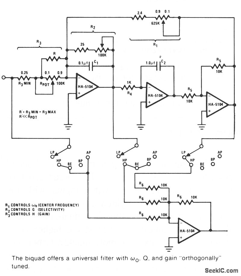
The Biquad consists of two successive integration stages followed by an inverting stage. The entire configuration includes a feedback loop from the front to the back, with resistor R1 primarily responsible for controlling the center frequency, fo. The first stage...
Dual low-voltage power supply circuit breaker electromagnetic closing each vote circuit
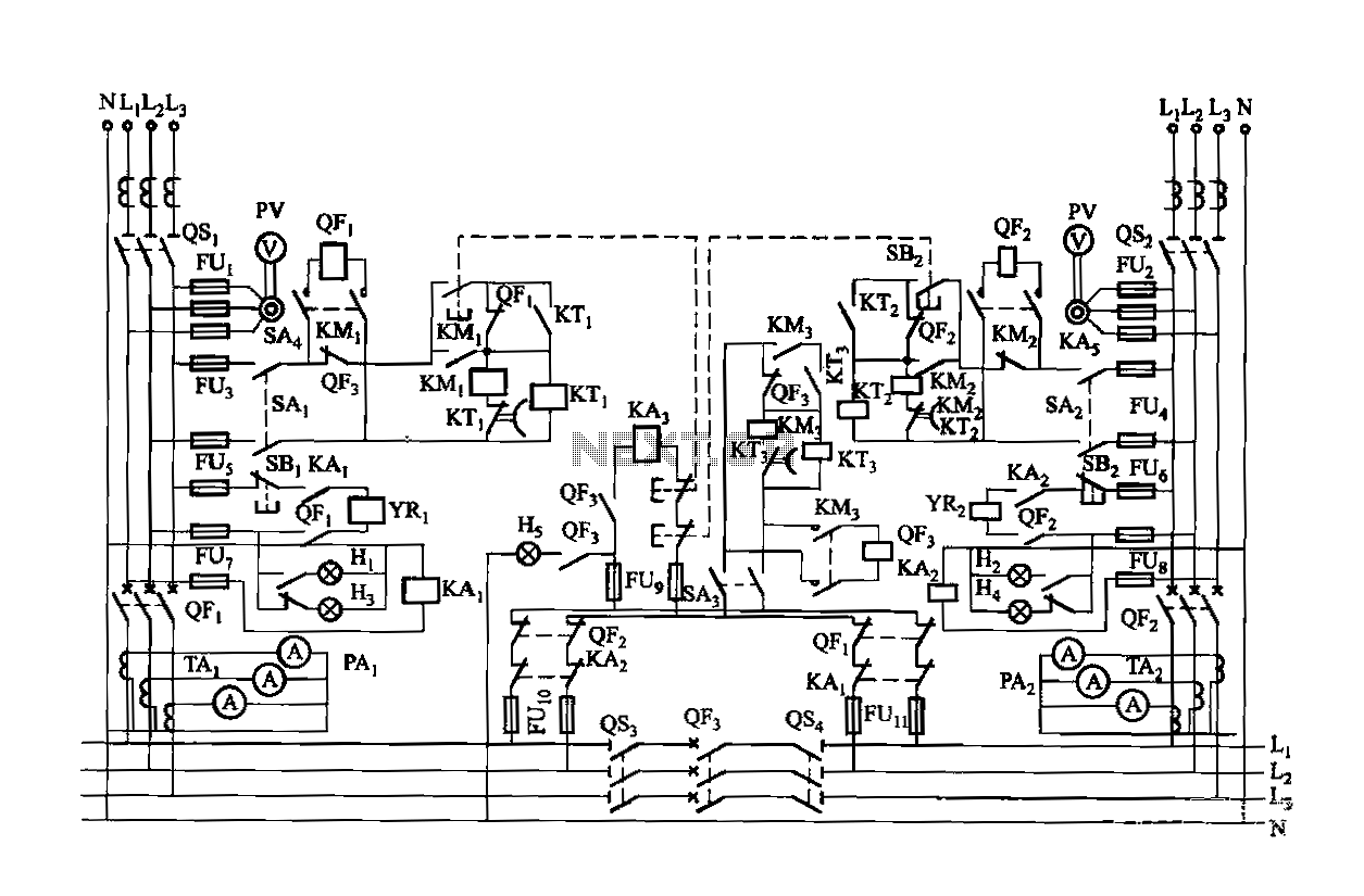
Dual power is provided for each complex, as the load is supplied through a two-way power system. In the event of a power outage, the contact switches transition from a closed position, allowing the power supply circuit to bear the...
Dual Power Supply 15V
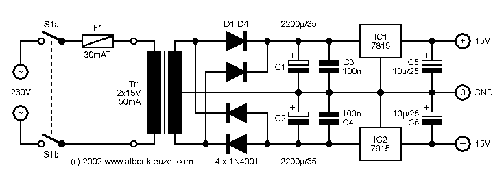
The 7915 (at least the "made in Morocco" I used) needs a small load (some mA) to work correctly. If you get funny voltages (-18.4V or so), put a resistor from the 7915 output to ground (2k2 works good). Or...
Regulated Dual Power Supply Circuit Using Regulator IC
The circuit is designed to regulate a dual power supply that provides +12V and -12V from the AC mains. Such a power supply is an essential tool for an electronic hobbyist's workbench. The schematic of the circuit includes components such...
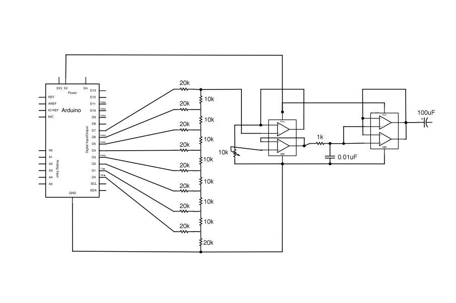
Arduino Vocal Effects Box
This Arduino-powered vocal effects box pitch shifts and distorts incoming audio signals to produce a wide variety of vocal effects. This project is an experiment with real-time digital signal processing using Arduino. It samples an incoming microphone signal at a...
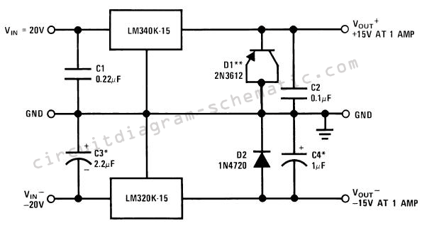
dual power supply circuit
The circuit consists of a series of dual power supplies, providing a symmetrical ±15V supply for linear circuits. The same principle is applicable to non-symmetrical supplies, such as 5.0V and -12V regulators, which are used in applications like registers. To...
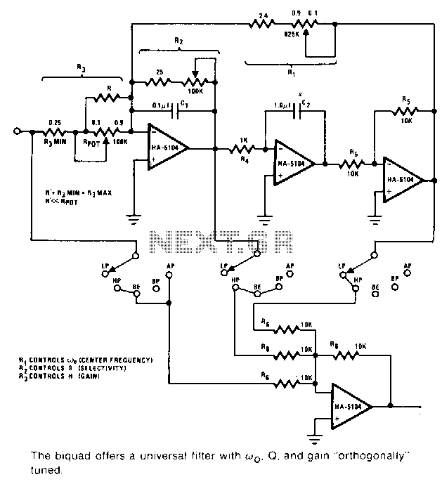
Biquad-audio-filter
This universal filter provides low-pass, high-pass, bandpass, band elimination, and all-pass functions. The Biquad consists of two successive integration stages followed by an inverting stage. The entire system features a feedback loop from the front to the back, primarily controlled...

Dual 50V/5A Universal Power Supply
The transformer has two primary windings and six secondary windings; the two 120-VAC primary windings and the 6.3-VAC secondary windings are connected in parallel. Modules A and B are identical; therefore, only the components of Module A are specified. Module...
Audio Beat Detect ?« Electronic Product Design
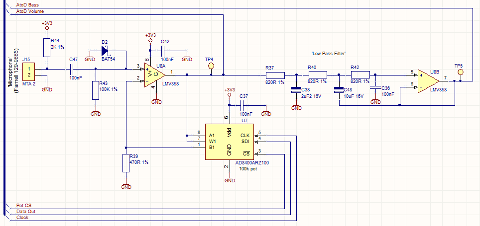
This circuit employs a digital potentiometer to enable the microcontroller to automatically adjust the circuit's gain according to the ambient audio volume. However, a standard potentiometer can be used if automatic adjustment is unnecessary. The low-pass filter design is based...