


By the PGA204 205 op amp OPA602 programmable AC coupled amplifier
#PGA204
#PGA205
#OPA602
#programmable amplifier
#AC coupled
#feedback
#op amp
#amplifier circuit
#signal conditioning
#instrumentation
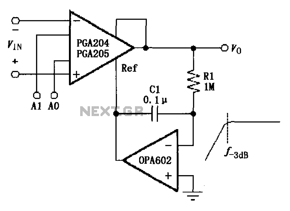
Description: The circuit depicted in the figure features a programmable amplifier utilizing the PGA204/205 operational amplifiers in conjunction with the OPA602. The OPA602 op-amp is configured to establish a feedback reference point, while external components, specifically the capacitor C1 and resistor R1, contribute to the AC characteristics of the circuit. The -3 dB frequency is determined by the equation f-3dB = 1/(2πR1C1), resulting in a cutoff frequency of approximately 1.59 Hz. This configuration effectively forms an AC-coupled instrumentation amplifier. Gain settings for the circuit are controlled via the A0 and A1 pins of the PGA204/205, allowing for the amplification of the input signal, which is subsequently output from the PGA204/205.
The described circuit integrates a programmable gain amplifier (PGA) and an operational amplifier (OPA) to create a versatile instrumentation amplifier with specific AC coupling characteristics. The PGA204/205 series offers configurable gain settings through digital control, enabling precise adjustments for various applications. The OPA602, known for its high-speed and low-noise performance, serves as the core amplification component.
In the configuration, the feedback loop established by the OPA602 ensures stability and linearity in the amplification process. The external components, C1 and R1, play a crucial role in determining the frequency response of the amplifier. The calculated -3 dB point of 1.59 Hz indicates that the amplifier is optimized for low-frequency signal processing, making it suitable for applications such as sensor signal conditioning or biomedical instrumentation.
The gain settings provided by A0 and A1 allow for multiple gain configurations, enhancing the amplifier's adaptability to different input signal levels. This flexibility is particularly beneficial in environments where signal amplitudes may vary significantly. The output from the PGA204/205 can be further processed or utilized in subsequent stages of a signal processing chain, depending on the overall system requirements.
Overall, the combination of the PGA204/205 and OPA602 in this AC-coupled instrumentation amplifier configuration offers a robust solution for low-frequency signal amplification with programmable gain capabilities, suitable for a wide range of electronic applications. As shown in FIG exchange by PGA204/205 op amp OPA602 constituted coupled programmable amplifier. The OPA602 op amp circuit to form a feedback Ref foot while external op amp OPA 602 C1, R1 after having AC characteristics, f-3db 1/2 R1C1 1.59Hz, thus constituting an AC-coupled instrumentation amplifier. By A0, A1 for PGA204/205 Gain settings, signal input through the PGA204/205 amplified output.
The described circuit integrates a programmable gain amplifier (PGA) and an operational amplifier (OPA) to create a versatile instrumentation amplifier with specific AC coupling characteristics. The PGA204/205 series offers configurable gain settings through digital control, enabling precise adjustments for various applications. The OPA602, known for its high-speed and low-noise performance, serves as the core amplification component.
In the configuration, the feedback loop established by the OPA602 ensures stability and linearity in the amplification process. The external components, C1 and R1, play a crucial role in determining the frequency response of the amplifier. The calculated -3 dB point of 1.59 Hz indicates that the amplifier is optimized for low-frequency signal processing, making it suitable for applications such as sensor signal conditioning or biomedical instrumentation.
The gain settings provided by A0 and A1 allow for multiple gain configurations, enhancing the amplifier's adaptability to different input signal levels. This flexibility is particularly beneficial in environments where signal amplitudes may vary significantly. The output from the PGA204/205 can be further processed or utilized in subsequent stages of a signal processing chain, depending on the overall system requirements.
Overall, the combination of the PGA204/205 and OPA602 in this AC-coupled instrumentation amplifier configuration offers a robust solution for low-frequency signal amplification with programmable gain capabilities, suitable for a wide range of electronic applications. As shown in FIG exchange by PGA204/205 op amp OPA602 constituted coupled programmable amplifier. The OPA602 op amp circuit to form a feedback Ref foot while external op amp OPA 602 C1, R1 after having AC characteristics, f-3db 1/2 R1C1 1.59Hz, thus constituting an AC-coupled instrumentation amplifier. By A0, A1 for PGA204/205 Gain settings, signal input through the PGA204/205 amplified output.
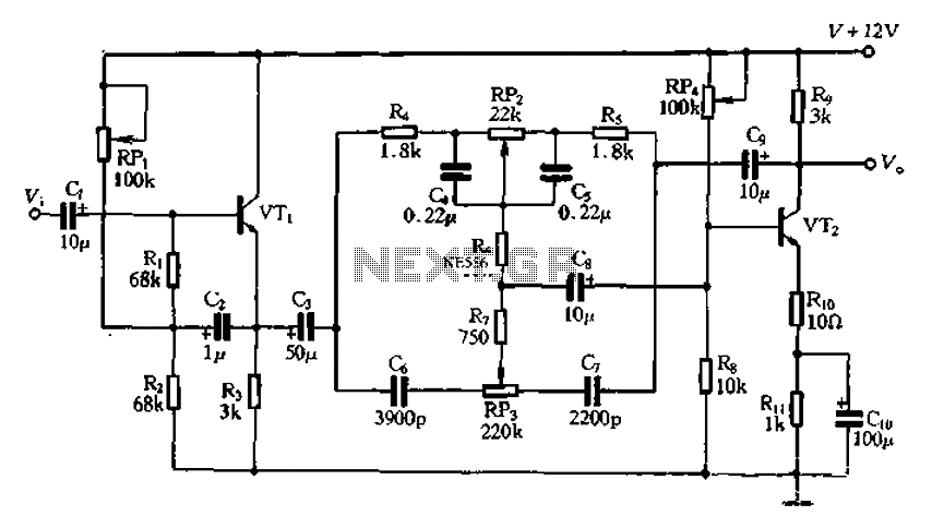
Attenuation feedback tone circuit
The attenuation circuit is a feedback tone control system that consists of transistors and an RC network. The circuit includes a low tone control potentiometer (RP2) and a treble control potentiometer (RP3). The bass control is influenced by resistor R5,...
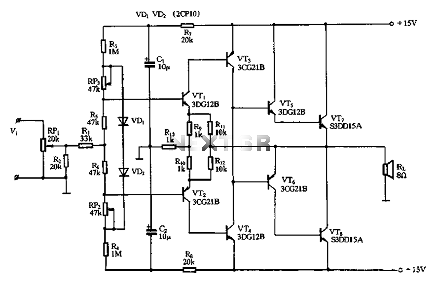
Pure CL B amplifier circuit
The circuit utilizes diode VDi, f Pooh to stabilize the base bias of transistors VTi and VT2, ensuring a more stable quiescent point when the supply voltage is within a specific range. In the event of temperature fluctuations, the two...
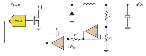
Did You Buffer The Buffered Buffer
Cypress' Dave Van Ess cautions circuit designers about the excessive and careless use of operational amplifiers, providing examples and circuit theory.
Operational amplifiers (op-amps) are widely utilized in various electronic circuits due to their versatility and performance characteristics. However, the overuse...
op amp Op amp analysis question
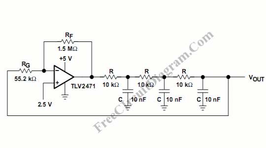
The circuit was reverse engineered from old equipment. The operational amplifier stage appears to function as a comparator or oscillator, comparing a time-varying voltage $V_0$, influenced by capacitors, against a 2.5 V reference from a square wave generator with a...
Programable amplifier
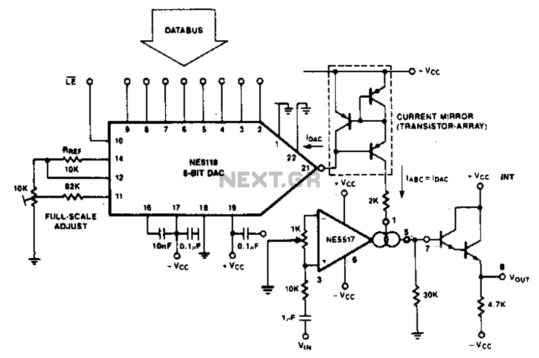
The purpose of the following application is to demonstrate how the NE5517 operates in conjunction with a DAC. The application utilizes the NE5118, an 8-bit DAC with current output, featuring an input register that makes this device fully micro-compatible. The...
Peak Reading Audio Level Meter
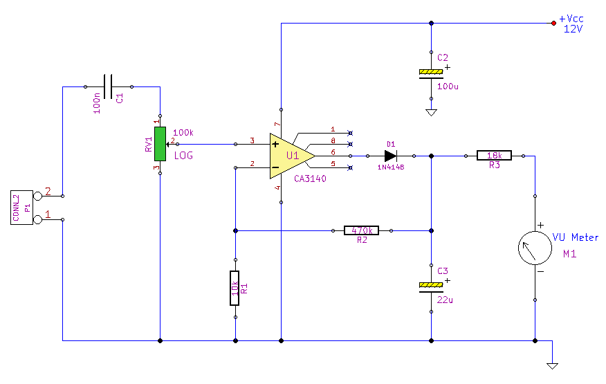
This simple circuit, designed with a minimal component count, indicates peak audio response on an analog meter, similar to a tape recorder's meter. It employs an operational amplifier configured as a non-inverting amplifier, with the addition of a diode in...
Trap MC33171
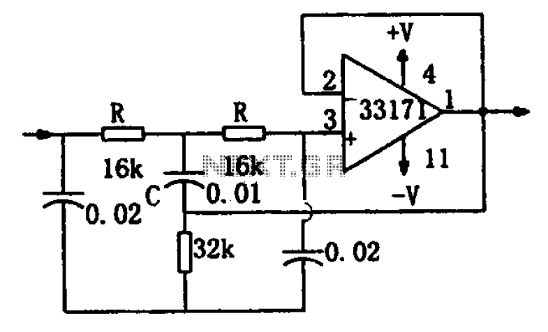
A chopper circuit is illustrated in the figure. The circuit utilizes a high-performance operational amplifier, MC33171, to create a trap. This device features a wide bandwidth and a high conversion rate. The component values can be modified by adjusting the...
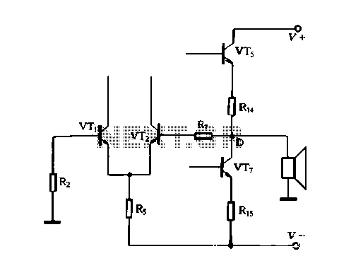
OCL yourself feedback amplifier analysis
The DC feedback circuit is illustrated in Figure 1-31. In this circuit, resistor R7 is connected to the output terminal, which is the midpoint of the static differential input stage voltage Vr, between the base terminals. This configuration represents a...
OCL yourself feedback amplifier analysis
The DC feedback circuit is illustrated in Figure 1-31. In this circuit, resistor R7 is connected to the output terminal, which is the midpoint of the static differential input stage voltage Vr, between the base terminals. This configuration represents a...