


CIRCUIT ALLOWS SLEW RATE CONTROL
#slew rate control
#op-amp
#signal processing
#servo applications
#error signal
#power rails
#positive rate
#negative rate
#control circuit
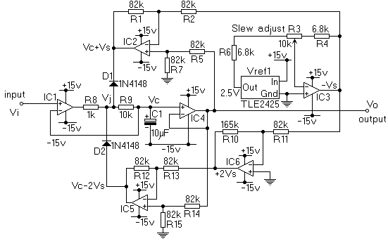
Description: This circuit will impose a maximum slew rate on a signal; positive and negative rates can be independently controlled. The circuit is useful in servo applications where the error signal needs to be limited to be within the power rails to ensure predictable operation.
The described circuit functions as a slew rate limiter, which is critical in various electronic applications, particularly in servo control systems. The primary objective of this circuit is to restrict the rate of change of the output signal, thereby preventing abrupt changes that could lead to instability in the system.
The circuit typically consists of operational amplifiers (op-amps), resistors, and capacitors configured in such a way that the output signal's rise and fall times are controlled. The op-amps are arranged to compare the input signal with a feedback signal derived from the output. By adjusting the feedback loop, the maximum slew rate can be set for both the positive and negative transitions of the signal independently.
For instance, the positive slew rate can be controlled by a resistor-capacitor (RC) network that determines how quickly the output can rise when the input signal transitions from a low to a high state. Similarly, a separate RC network can be used to control the negative slew rate, allowing for tailored performance based on application requirements.
In practical applications, this circuit is implemented to ensure that the servo system does not exceed the limits of the power supply rails. By limiting the slew rate, the circuit enhances the stability and predictability of the servo response, minimizing overshoot and oscillations that could occur if the system were allowed to respond too quickly to changes in the input signal.
In summary, this circuit serves an essential role in maintaining controlled signal transitions in servo applications, promoting reliable operation within the defined power limits.This circuit (figure 1) will impose a maximum slew rate on a signal; positive and negative rates can be independently controlled. The circuit is useful in servo applications where the error signal needs to be limited to be within the power rails to ensure predictable operation.
The described circuit functions as a slew rate limiter, which is critical in various electronic applications, particularly in servo control systems. The primary objective of this circuit is to restrict the rate of change of the output signal, thereby preventing abrupt changes that could lead to instability in the system.
The circuit typically consists of operational amplifiers (op-amps), resistors, and capacitors configured in such a way that the output signal's rise and fall times are controlled. The op-amps are arranged to compare the input signal with a feedback signal derived from the output. By adjusting the feedback loop, the maximum slew rate can be set for both the positive and negative transitions of the signal independently.
For instance, the positive slew rate can be controlled by a resistor-capacitor (RC) network that determines how quickly the output can rise when the input signal transitions from a low to a high state. Similarly, a separate RC network can be used to control the negative slew rate, allowing for tailored performance based on application requirements.
In practical applications, this circuit is implemented to ensure that the servo system does not exceed the limits of the power supply rails. By limiting the slew rate, the circuit enhances the stability and predictability of the servo response, minimizing overshoot and oscillations that could occur if the system were allowed to respond too quickly to changes in the input signal.
In summary, this circuit serves an essential role in maintaining controlled signal transitions in servo applications, promoting reliable operation within the defined power limits.This circuit (figure 1) will impose a maximum slew rate on a signal; positive and negative rates can be independently controlled. The circuit is useful in servo applications where the error signal needs to be limited to be within the power rails to ensure predictable operation.
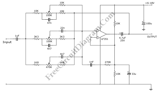
Single Op-Amp 3 Band Equalizer circuit
This is a 3 Band Equalizer circuit designed to control the treble, midrange, and bass frequencies. The circuit utilizes a single operational amplifier (op-amp).
The 3 Band Equalizer circuit serves to enhance audio signals by allowing users to adjust specific frequency...
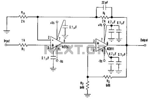
Fast Composite Amplifier Circuit
An ultra-low-noise, low-distortion operational amplifier, the AD797, is combined with the ADS 11 operational amplifier, which provides high bandwidth and a 100-mA output drive capability. This composite amplifier circuit is effective for driving high-resolution ADCs and ATE systems. The fast...
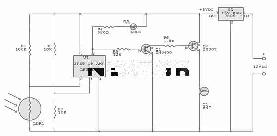
Mooring Light Controller
Integrated-circuit U1-an LF351 or 741 op amp-is used as a comparator to control the light. Resistors R2 and R3 provide a reference voltage of about 2.5 volts at pin 3 of U1. When daylight falls on light-dependent resistor LDR1, its...
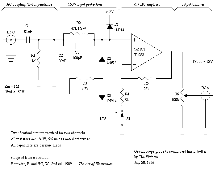
Capacitor in parallel with resistor on xoscope amplifier schematic
For capacitor C3, a 100pF capacitor is placed across resistor R2. The circuit functions similarly to previous configurations, although no explanation is provided. The purpose of this component may be self-evident to experienced users, but it may not be clear...
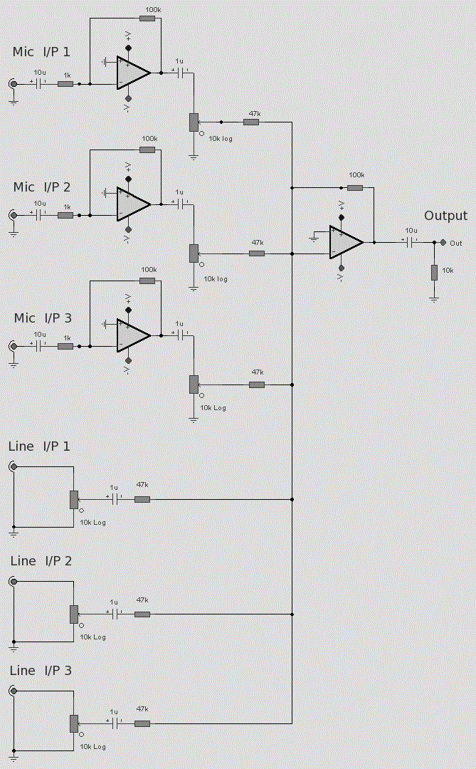
op amp 6 line audio mixer circuit
As with any audio mixer circuit, a slight loss is always introduced. The final summing amplifier has a gain of 2 or 6dB to overcome this. The input line level should be around 200mV RMS. The mic inputs are amplified...
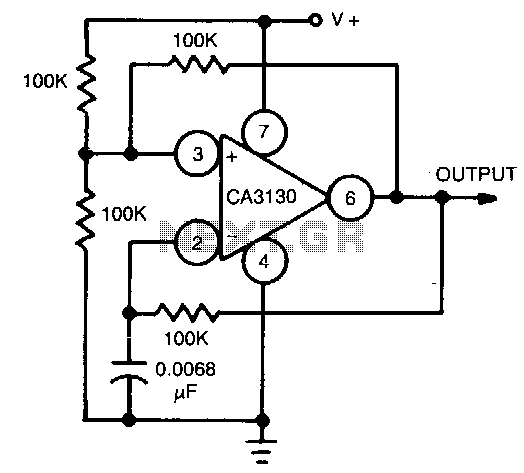
Classic-op-amp-astable-multivibrator
This circuit utilizes the CA3130 BiMOS operational amplifier, which operates at a frequency of 1 kHz. It features a rail-to-rail output swing, ensuring that the output can reach the supply voltage levels. The frequency of operation remains independent of supply...
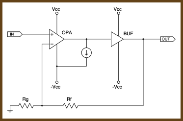
Biasing Op-Amps into Class A
"Class A" refers to configuring an amplifier so that its output devices remain turned on all the time. This reduces thermal variation and eliminates crossover distortion, which makes the chip perform better. To bias an op-amp into class A, you...
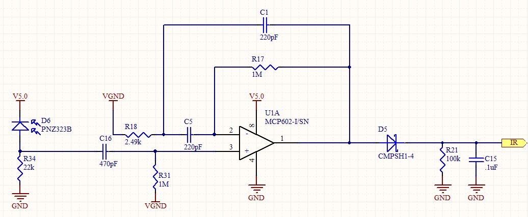
op amp IR Demodulator Design
Designing an infrared (IR) demodulator circuit to replace the one shown in this question. The goal is to demodulate a simple IR signal modulated at 32.678 kHz, with the requirement of detecting the presence of the signal without packet decoding....
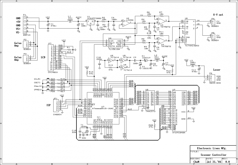
Home Built Laser Projector
This document outlines the servo amplifier and its circuit diagram. It describes a straightforward operational amplifier circuit that integrates both a power amplifier and a small signal amplifier on the same board. Care must be taken to avoid unintended coupling...