


Current-Driven Sallen Key FilterCircuit
#Sallen-Key filter
#op-amp
#low-pass filter
#current-driven
#analog filter
#signal processing
#active filter
#circuit design
#filter topology
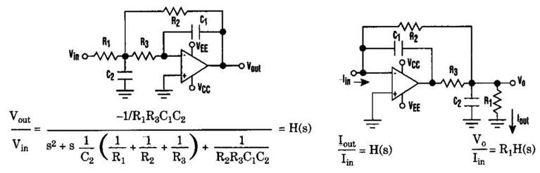
Description: Current-Driven Sallen-Key Filter Circuit Diagram. The low-pass Sallen-Key filter is a staple for designers because it contains few components (A).
The Sallen-Key filter is a widely used active filter topology that employs operational amplifiers (op-amps) to achieve desired filtering characteristics. The current-driven variant of the Sallen-Key filter enhances performance by utilizing a current source instead of a voltage source, which can improve linearity and reduce distortion in audio applications.
In a typical Sallen-Key low-pass filter configuration, two resistors and two capacitors are arranged in a manner that defines the cutoff frequency and the quality factor (Q) of the filter. The op-amp serves as a voltage follower, providing high input impedance and low output impedance, which is essential for maintaining the integrity of the signal being filtered.
The circuit can be described as follows:
1. **Components**: The essential components of the current-driven Sallen-Key filter include two resistors (R1 and R2), two capacitors (C1 and C2), and an operational amplifier (U1). Additionally, a current source (I) is used to drive the input signal.
2. **Configuration**: The first capacitor (C1) is connected to the non-inverting input of the op-amp, while the second capacitor (C2) is connected in feedback from the output to the inverting input. The resistors (R1 and R2) are placed in series with the capacitors to set the filter characteristics.
3. **Transfer Function**: The transfer function of the filter can be derived from the component values and describes how the output signal relates to the input signal across different frequencies. The cutoff frequency (fc) is determined by the formula:
\[
f_c = \frac{1}{2\pi\sqrt{R1 \cdot R2 \cdot C1 \cdot C2}}
\]
This relationship allows designers to choose component values to achieve the desired frequency response.
4. **Applications**: The current-driven Sallen-Key low-pass filter is particularly useful in audio processing, signal conditioning, and data acquisition systems, where clean and precise filtering of signals is critical.
5. **Advantages**: The primary advantages of this filter topology include simplicity in design, ease of implementation, and the ability to achieve high performance with minimal component count. The use of a current source can also offer improved performance characteristics compared to traditional voltage-driven filters.
This Sallen-Key filter design exemplifies a balance between simplicity and functionality, making it a preferred choice in various electronic applications.Current-Driven Sallen Key Filter Circuit Diagram he low-pass Sallen-Key filter is staple for designers because it contains few components (A). By redesigning the filter,
The Sallen-Key filter is a widely used active filter topology that employs operational amplifiers (op-amps) to achieve desired filtering characteristics. The current-driven variant of the Sallen-Key filter enhances performance by utilizing a current source instead of a voltage source, which can improve linearity and reduce distortion in audio applications.
In a typical Sallen-Key low-pass filter configuration, two resistors and two capacitors are arranged in a manner that defines the cutoff frequency and the quality factor (Q) of the filter. The op-amp serves as a voltage follower, providing high input impedance and low output impedance, which is essential for maintaining the integrity of the signal being filtered.
The circuit can be described as follows:
1. **Components**: The essential components of the current-driven Sallen-Key filter include two resistors (R1 and R2), two capacitors (C1 and C2), and an operational amplifier (U1). Additionally, a current source (I) is used to drive the input signal.
2. **Configuration**: The first capacitor (C1) is connected to the non-inverting input of the op-amp, while the second capacitor (C2) is connected in feedback from the output to the inverting input. The resistors (R1 and R2) are placed in series with the capacitors to set the filter characteristics.
3. **Transfer Function**: The transfer function of the filter can be derived from the component values and describes how the output signal relates to the input signal across different frequencies. The cutoff frequency (fc) is determined by the formula:
\[
f_c = \frac{1}{2\pi\sqrt{R1 \cdot R2 \cdot C1 \cdot C2}}
\]
This relationship allows designers to choose component values to achieve the desired frequency response.
4. **Applications**: The current-driven Sallen-Key low-pass filter is particularly useful in audio processing, signal conditioning, and data acquisition systems, where clean and precise filtering of signals is critical.
5. **Advantages**: The primary advantages of this filter topology include simplicity in design, ease of implementation, and the ability to achieve high performance with minimal component count. The use of a current source can also offer improved performance characteristics compared to traditional voltage-driven filters.
This Sallen-Key filter design exemplifies a balance between simplicity and functionality, making it a preferred choice in various electronic applications.Current-Driven Sallen Key Filter Circuit Diagram he low-pass Sallen-Key filter is staple for designers because it contains few components (A). By redesigning the filter,

Tunable active filter
The high-pass and low-pass outputs cover the range of 300 Hz to 3000 Hz. The potentiometers must have a reverse log taper. The fixed-frequency active filter is summed in the fourth operational amplifier to provide a notch center frequency of...
Open-Loop Peak Detector Circuit
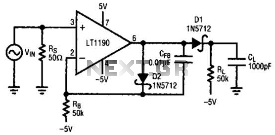
In this open-loop design, the detector diode is D1, and a level-shifting or compensating diode is D2. Load resistor RL is connected to -5 V, and an identical bias resistor RB is used to bias the compensating diode, also connected...

Doppler Rdf
The power supply consists of a 7812 voltage regulator followed by an operational amplifier (op-amp) configured to output 6V, which serves as a midpoint supply voltage for the audio op-amp stages. A 12V regulator is deemed excessive for battery-powered applications....
3 Band Graphic Equalizer
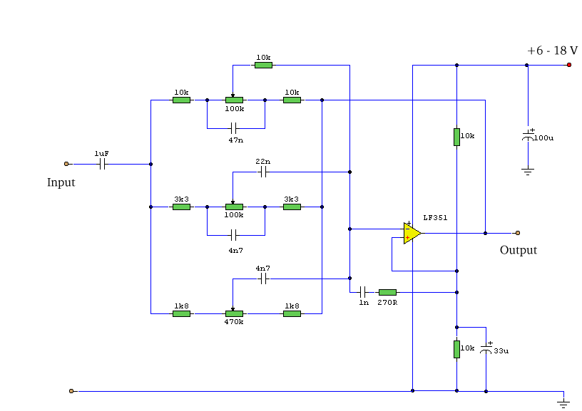
This simple equalizer circuit utilizes a single operational amplifier (op-amp) to provide three distinct frequency ranges: low frequency, mid frequency, and high frequency. With the specified component values, the circuit is capable of delivering an approximate gain of +/-20dB at...
IC4030-4031 Typical Operating Circuit Schematic and Datasheet
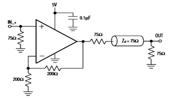
The diagram below illustrates a typical operating circuit for the video line driver using the IC4030/4031 schematic. It incorporates the MAX4030E/MAX4031E, which are unity-gain stable operational amplifiers that offer high-speed performance, rail-to-rail outputs, and 15kV ESD protection, as stated in...
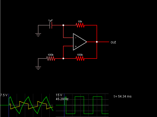
Relaxation Oscillator
This circuit is an oscillator that generates a square wave. The operational amplifier (op-amp) begins with its two inputs in an undefined state, starting with the non-inverting input slightly higher than the inverting input. The op-amp significantly amplifies this difference,...
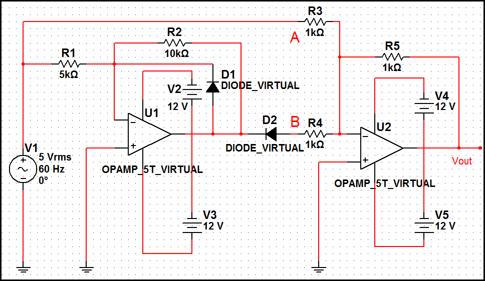
Sine to rectangular wave conversion circuit
The optimal operational amplifier circuit used to convert a sine waveform into a rectangular waveform is the Schmitt trigger circuit.
The Schmitt trigger circuit is a vital component in signal processing, particularly for converting analog signals into digital signals. It utilizes...
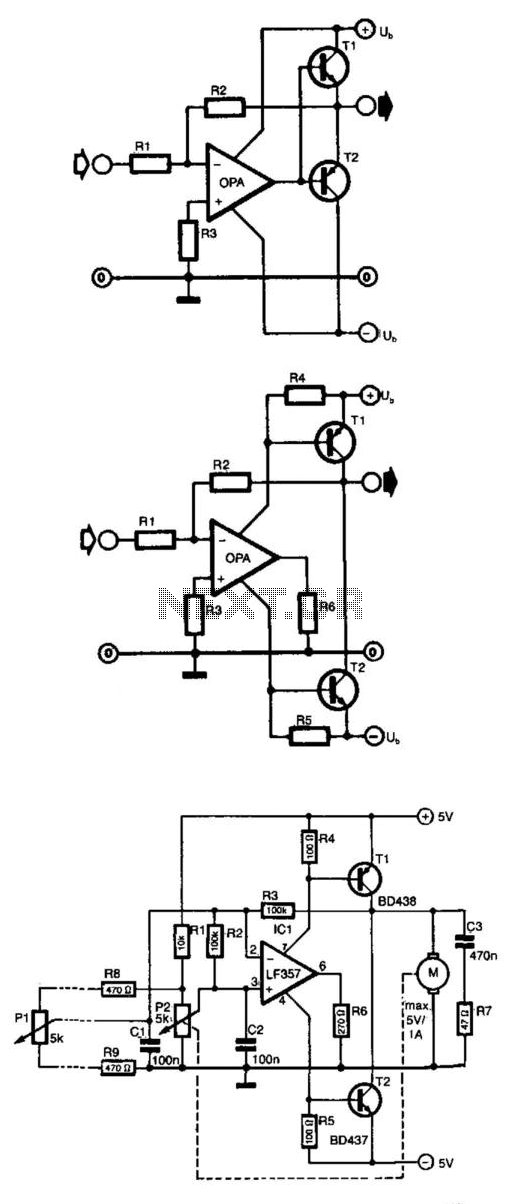
Op Amp Power Driver
Frequently, the output current of an operational amplifier is inadequate for applications such as driving a small motor or loudspeaker. This issue is typically resolved by adding an emitter follower to the circuit. However, this configuration does not allow the...
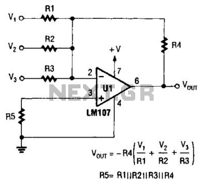
Inverting Summing Amplifier Circuit
The output of Ul is the sum of Vv, multiplied by the ratio of Rx to Rv, RJRV, and respectively. Resistors R1, R2, and R3 are selected as required for individual gains. Additionally, R4 influences the gain of all these...