


High-precision high-impedance instrument OPA2111 amplifier circuit
#OPA2111
#high-precision
#high-impedance
#instrumentation amplifier
#differential amplifier
#gain stage
#common-mode voltage
#voltage amplification
#signal conditioning
#precision measurement

Description: This document illustrates the configuration of the high-precision, high-impedance OPA2111 amplifier. The total voltage circuit is designed for a magnification of Av = 10 (1 + 2R2 / R1), achieving a total gain of 1000 times. A gain stage of 10 in the differential amplifier circuit is utilized to extend the input common-mode voltage range of the instrumentation amplifier to 10V.
The OPA2111 is a precision operational amplifier characterized by its low noise and high input impedance, making it suitable for applications requiring accurate signal amplification. The configuration described utilizes a differential amplifier setup, which is essential for rejecting common-mode signals while amplifying the desired differential signal.
In this circuit, the gain is determined by the resistors R1 and R2, with the formula for voltage gain being Av = 10 (1 + 2R2 / R1). This configuration allows for a significant amplification factor of 1000, which is beneficial in applications where signal levels are low and need to be boosted for further processing or analysis.
The differential amplifier stage enhances the common-mode voltage range, allowing the instrumentation amplifier to handle input signals that may vary significantly without distortion or loss of fidelity. By extending the common-mode input voltage range to 10V, the amplifier can effectively process signals from various sources, including sensors and transducers, which may operate within this voltage range.
Overall, the OPA2111 amplifier configuration presented is an effective solution for applications requiring high precision and high input impedance, ensuring accurate signal amplification while maintaining the integrity of the input signal.Shown for the high-precision, high-impedance instrument OPA2111 amplifier configuration. Total voltage circuit illustrated magnification Av = 10 (1 + 2R2 / R1) = 1000 times. A gain stage 10 of the differential amplifier circuit is to expand the instrumentation amplifiers input common-mode voltage range of 10V.
The OPA2111 is a precision operational amplifier characterized by its low noise and high input impedance, making it suitable for applications requiring accurate signal amplification. The configuration described utilizes a differential amplifier setup, which is essential for rejecting common-mode signals while amplifying the desired differential signal.
In this circuit, the gain is determined by the resistors R1 and R2, with the formula for voltage gain being Av = 10 (1 + 2R2 / R1). This configuration allows for a significant amplification factor of 1000, which is beneficial in applications where signal levels are low and need to be boosted for further processing or analysis.
The differential amplifier stage enhances the common-mode voltage range, allowing the instrumentation amplifier to handle input signals that may vary significantly without distortion or loss of fidelity. By extending the common-mode input voltage range to 10V, the amplifier can effectively process signals from various sources, including sensors and transducers, which may operate within this voltage range.
Overall, the OPA2111 amplifier configuration presented is an effective solution for applications requiring high precision and high input impedance, ensuring accurate signal amplification while maintaining the integrity of the input signal.Shown for the high-precision, high-impedance instrument OPA2111 amplifier configuration. Total voltage circuit illustrated magnification Av = 10 (1 + 2R2 / R1) = 1000 times. A gain stage 10 of the differential amplifier circuit is to expand the instrumentation amplifiers input common-mode voltage range of 10V.
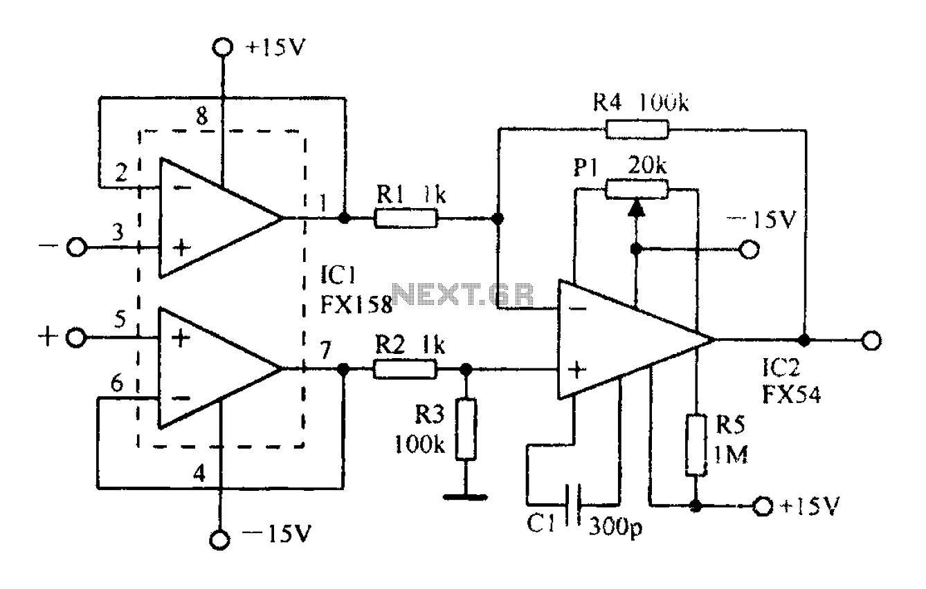
A differential amplifier having input impedance equal to the circuit diagram
A differential amplifier with input impedance as indicated in the circuit diagram.
A differential amplifier is a crucial component in various electronic applications, primarily used to amplify the difference between two input voltages while rejecting any common-mode signals. This characteristic makes...
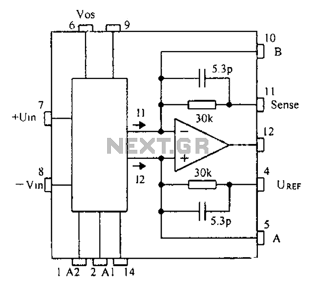
Based CNC programming gain instrumentation amplifier PGA202 203 schematic
Based on the CNC programming, a gain instrumentation amplifier circuit diagram utilizing the PGA202/203 is presented.
The PGA202/203 series of programmable gain amplifiers are designed for high-performance applications requiring precise signal amplification. These integrated circuits offer a wide range of programmable...
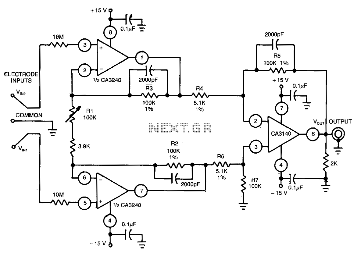
Biomedical-instrumentation-differential-amplifier
This differential amplifier utilizes the isolated high-impedance inputs of the CA3420 BiMOS operational amplifier. The input current of the CA3240 is limited to a maximum of 50 pA, allowing for the use of 10-MΩ resistors in series with the input...
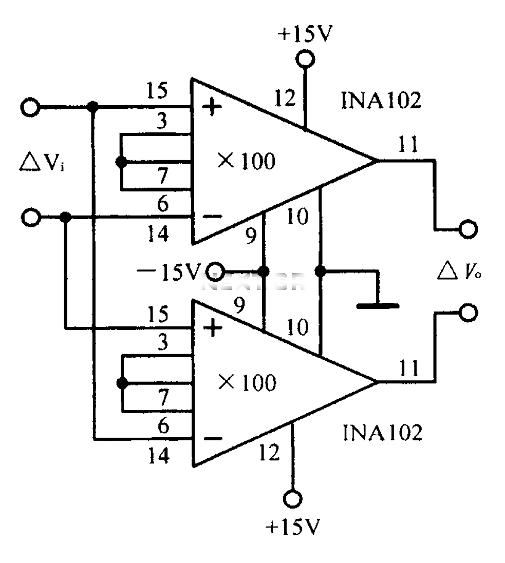
A differential input differential output amplifying circuit diagram
A differential input differential output amplifying circuit diagram.
A differential input differential output (DIDO) amplifier is a type of operational amplifier configuration that is designed to amplify the difference between two input signals while rejecting any signals that are common to...
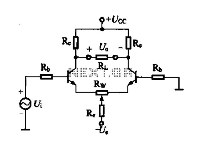
Differential amplifier circuit four connection methods and characteristics of comparison c
Differential amplifier circuit with four connection methods and characteristics for comparison. The circuit exhibits magnification with a single tube when symmetrical. Additionally, CMRR (Common Mode Rejection Ratio) is adapted from single-ended input to a double-ended output.
The differential amplifier is a...
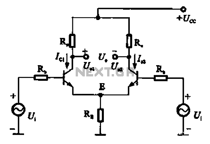
Common mode signal of emitter-coupled differential amplifier circuit a
The common mode signal of an emitter-coupled differential amplifier circuit assumes that two equal small increases of the same polarity signal, referred to as the common mode signal, occur simultaneously. This results in an increase in the potential at point...
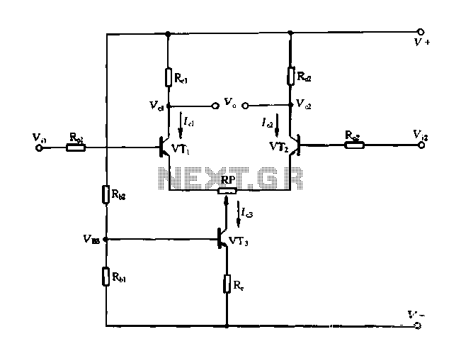
Differential circuit with constant current
A differential amplifier with a constant current source is illustrated in Figure 1-27. As long as capacitor C3 is maintained at a constant value, capacitors C1 and C2 cannot be simultaneously increased or decreased, preventing voltage drift. The differential circuit...
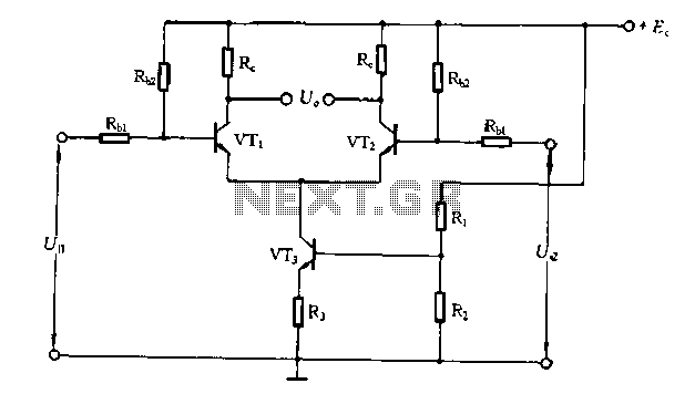
Differential amplifier circuit has a constant current source
The differential amplifier circuit features a constant current source.
The differential amplifier is a fundamental building block in analog electronics, utilized for amplifying the difference between two input voltages while rejecting any signals that are common to both inputs. Central to...
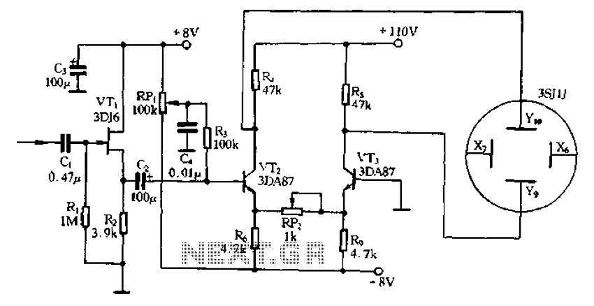
Application of the differential amplifier circuit in a simple small oscilloscope
Application of the differential amplifier circuit in a simple small oscilloscope.
The differential amplifier circuit is a crucial component in the design of a simple small oscilloscope. This circuit is designed to amplify the difference between two input voltage signals while...