


Instrument preamp
#instrument preamp
#op-amp
#feedback loop
#voltage gain
#tone control
#input impedance
#bass adjustment
#audio signal
#inverting input
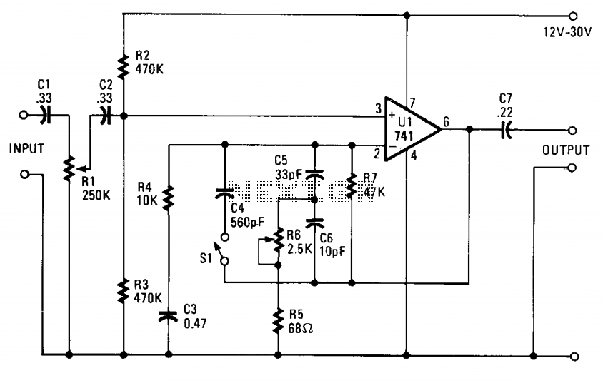
Description: The input impedance corresponds to the value of potentiometer Rl. If the instrument exhibits excessive deep bass, it is advisable to change capacitor C1 to 0.5 mF. The component that may seem like an additional element in the feedback loop is a tone control that enhances brightness. The fundamental feedback from the output of the operational amplifier (pin 6) to the inverting input (pin 2) includes resistor R7 and the series connection of resistor R4 and capacitor C3, which collectively yield a voltage gain of nearly 5 (approximately 14 dB). This configuration provides more amplification than typically required. If the circuit lacks sufficient bass response, it is recommended to increase the value of capacitor C3 to a range of 1 to 10 µF. Starting with a value of 1 µF and gradually increasing it will help achieve the desired bass effect.
The circuit described involves an operational amplifier configured for feedback with a tone control feature that enhances the audio output. The input impedance is determined by the potentiometer Rl, allowing for adjustments based on the connected load or desired sensitivity. The choice of capacitor C1 is critical; a reduction to 0.5 mF is suggested for instruments with pronounced deep bass to avoid overwhelming the audio output.
The feedback loop is essential for maintaining stability and defining the gain of the circuit. Resistor R7 plays a pivotal role in this feedback mechanism, while the combination of resistor R4 and capacitor C3 is responsible for setting the voltage gain to approximately 14 dB. This gain is significant as it amplifies the input signal, providing a robust output suitable for various audio applications.
For fine-tuning the bass response, capacitor C3's value can be adjusted. Increasing its capacitance from an initial 1 µF to a maximum of 10 µF allows for enhanced low-frequency performance. This adjustment should be made incrementally, observing the output to achieve the preferred bass characteristics. The overall design emphasizes flexibility and adaptability to varying audio requirements, making it suitable for a range of electronic audio devices.The input impedance is the value of potentiometer Rl. If your instrument has extra-deep bass, change capacitor Cl to 0.5 mF. What appears to be an extra part in the feedback loop is a brightening tone control. The basic feedback from the op amp's output (pin 6) to the inverting input (pin 2) consists of resistor R7, and the series connection of resistor R4 and capacitor C3, which produce a voltage gain of almost 5 (almost 14 dB). That should be more extra oomph than usually needed. If the circuit is somewhat short on bass response, increase the value of capacitor C3 to 1 to 10 µ. Start with 1 µ¥ and increase the value until you get the bass effect you want.
The circuit described involves an operational amplifier configured for feedback with a tone control feature that enhances the audio output. The input impedance is determined by the potentiometer Rl, allowing for adjustments based on the connected load or desired sensitivity. The choice of capacitor C1 is critical; a reduction to 0.5 mF is suggested for instruments with pronounced deep bass to avoid overwhelming the audio output.
The feedback loop is essential for maintaining stability and defining the gain of the circuit. Resistor R7 plays a pivotal role in this feedback mechanism, while the combination of resistor R4 and capacitor C3 is responsible for setting the voltage gain to approximately 14 dB. This gain is significant as it amplifies the input signal, providing a robust output suitable for various audio applications.
For fine-tuning the bass response, capacitor C3's value can be adjusted. Increasing its capacitance from an initial 1 µF to a maximum of 10 µF allows for enhanced low-frequency performance. This adjustment should be made incrementally, observing the output to achieve the preferred bass characteristics. The overall design emphasizes flexibility and adaptability to varying audio requirements, making it suitable for a range of electronic audio devices.The input impedance is the value of potentiometer Rl. If your instrument has extra-deep bass, change capacitor Cl to 0.5 mF. What appears to be an extra part in the feedback loop is a brightening tone control. The basic feedback from the op amp's output (pin 6) to the inverting input (pin 2) consists of resistor R7, and the series connection of resistor R4 and capacitor C3, which produce a voltage gain of almost 5 (almost 14 dB). That should be more extra oomph than usually needed. If the circuit is somewhat short on bass response, increase the value of capacitor C3 to 1 to 10 µ. Start with 1 µ¥ and increase the value until you get the bass effect you want.
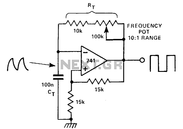
Adjustable oscillator
This circuit features two feedback paths around an operational amplifier (op-amp). One feedback path is a positive DC feedback that creates a Schmitt trigger, while the other incorporates a capacitor-resistor (CR) timing network. When the output voltage is +10 V,...
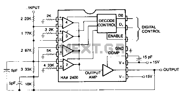
Inverting-programmable-gain-amplifier
This circuit can be programmed for a gain of 0, -1, -2, -4, or -8. This could also be accomplished with one input resistor and one feedback resistor per channel in the conventional manner, but this would require eight resistors...
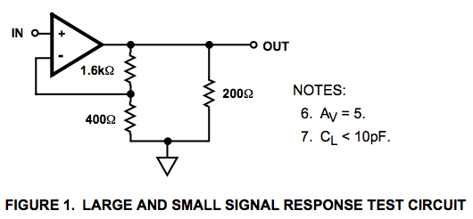
op amp Why the resistor in this op-amp circuit
Here is a circuit diagram for a signal response test circuit from the specification sheet for a HA-5195 operational amplifier. It appears to be a non-inverting amplifier circuit with a gain of 5, along with a 200-ohm resistor connecting Vout...
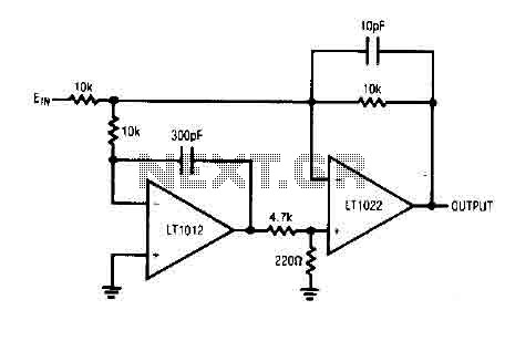
Unity gain Inverter amplifier circuit
The circuit comprises a low drift LT1012 device and a high-speed amplifier LT1022. It functions as a unity gain inverter, with the summing node located at the junction of three 10k ohm resistors. The circuit monitors the summing node of...
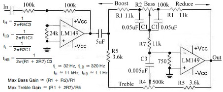
Active Audio Tone Control Circuit Design
This topic continues from the more general Passive Tone Control circuit, which begins using only passive filters. This circuit follows the previous design, although the component values are different and in an alternate configuration. An audio tone control combines both...
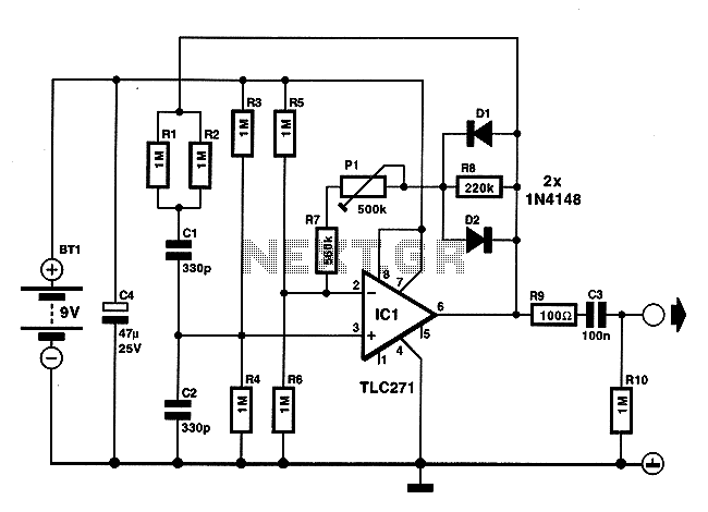
Low energy consumption audio signal generator
On occasions when it is necessary to determine if an amplifier is functioning, the most effective tool is an acoustic signal source with a frequency around 1 kHz. The specifications can be considered flexible, as rapid tests typically do not...
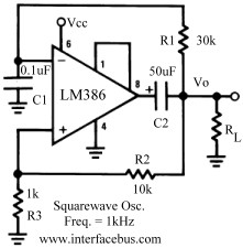
Op-Amp Pulse Generator Circuits
Several operational amplifier circuits are presented here, configured as square wave oscillators. A square wave is a periodic pulse train with a 50 percent duty cycle. The operational amplifier functions as a high-gain amplifier, and oscillation is achieved with minimal...
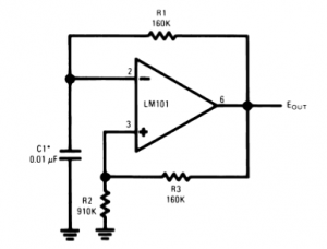
The Universal Linear Component
Operational amplifiers are the simplest and most effective means of executing a variety of linear functions, ranging from basic amplification to intricate analog computations.
Operational amplifiers (op-amps) are versatile components widely utilized in electronic circuits for various applications. These devices can...
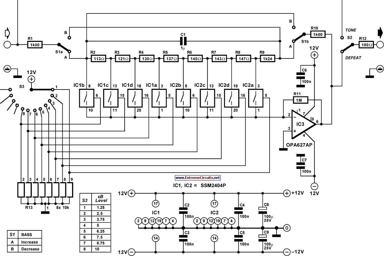
Accurate Bass Tone Control
A challenging issue in the design of traditional stereo tone controls is achieving synchronized movement of the potentiometers. Even minor discrepancies in synchronization can lead to phase and amplitude variations between the two audio channels. Additionally, linear potentiometers are commonly...