


liquid level sensor using 741 op amp
#741 op-amp
#liquid level sensor
#comparator
#fluid detection
#PCB sensor
#T1 transistor
#voltage output
#sensing circuit
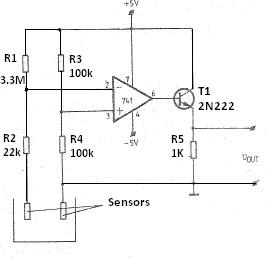
Description: This liquid level sensor circuit employs a common operational amplifier IC 741 configured as a comparator. When the sensor detects that the two fluid levels (which can be represented by two small pieces of PCB or similar conductors) are not present in the liquid, the output voltage of the operational amplifier 741 becomes negative, causing transistor T1 to turn off, resulting in an output voltage of 0 volts. Conversely, when the liquid level sensor is submerged in the fluid, the output voltage of the operational amplifier 741 rises to a few hundred millivolts, allowing transistor T1 to conduct and producing an output voltage of approximately 4 volts across resistor R5.
The circuit operates by utilizing the characteristics of the operational amplifier 741 as a comparator. In this configuration, two input terminals are monitored: one connected to a reference voltage and the other connected to the liquid level sensor. The reference voltage can be set using a voltage divider network to establish a threshold level that corresponds to the desired liquid level.
When the liquid level drops below the threshold, the voltage at the inverting input of the operational amplifier becomes greater than the voltage at the non-inverting input. As a result, the output of the operational amplifier swings to a negative voltage, which turns off transistor T1. Consequently, the voltage across resistor R5 drops to 0 volts, indicating a low liquid level.
On the other hand, when the liquid level rises and the sensor is submerged, the voltage at the non-inverting input increases, surpassing the reference voltage at the inverting input. This condition causes the output of the operational amplifier to rise, producing a positive voltage that turns on transistor T1. As T1 conducts, the output voltage across resistor R5 increases to approximately 4 volts, signaling that the liquid level is above the desired threshold.
This circuit can be easily implemented and modified for various applications by adjusting the reference voltage or using different types of sensors to suit specific liquid detection needs. The use of the operational amplifier 741 ensures reliable performance in detecting liquid levels, making it a suitable choice for various industrial and household applications.This circuit liquid level sensor is using a simple and common operational amplifier IC 741 used as a comparator. When the sensor two-fluid levels (you can use two small pieces of PCB or drivers of some of them) are not found in the fluid of the output voltage of operational amplifier 741 is negative and the T1 is blocked as a result 0 volt voltage
resistor R5. If the liquid level sensor is placed in the fluid of the output voltage of operational amplifier 741 is about a few hundred milli-volts and the transistor T1 conducts, which is an output voltage in the resistance around R5 4 volts.
The circuit operates by utilizing the characteristics of the operational amplifier 741 as a comparator. In this configuration, two input terminals are monitored: one connected to a reference voltage and the other connected to the liquid level sensor. The reference voltage can be set using a voltage divider network to establish a threshold level that corresponds to the desired liquid level.
When the liquid level drops below the threshold, the voltage at the inverting input of the operational amplifier becomes greater than the voltage at the non-inverting input. As a result, the output of the operational amplifier swings to a negative voltage, which turns off transistor T1. Consequently, the voltage across resistor R5 drops to 0 volts, indicating a low liquid level.
On the other hand, when the liquid level rises and the sensor is submerged, the voltage at the non-inverting input increases, surpassing the reference voltage at the inverting input. This condition causes the output of the operational amplifier to rise, producing a positive voltage that turns on transistor T1. As T1 conducts, the output voltage across resistor R5 increases to approximately 4 volts, signaling that the liquid level is above the desired threshold.
This circuit can be easily implemented and modified for various applications by adjusting the reference voltage or using different types of sensors to suit specific liquid detection needs. The use of the operational amplifier 741 ensures reliable performance in detecting liquid levels, making it a suitable choice for various industrial and household applications.This circuit liquid level sensor is using a simple and common operational amplifier IC 741 used as a comparator. When the sensor two-fluid levels (you can use two small pieces of PCB or drivers of some of them) are not found in the fluid of the output voltage of operational amplifier 741 is negative and the T1 is blocked as a result 0 volt voltage
resistor R5. If the liquid level sensor is placed in the fluid of the output voltage of operational amplifier 741 is about a few hundred milli-volts and the transistor T1 conducts, which is an output voltage in the resistance around R5 4 volts.
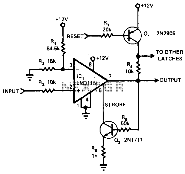
Comparator-latch
The main advantage of this circuit, in comparison to other comparators, is its capability to latch once the input surpasses a specified threshold level. When the input goes beyond this threshold, the output of the LM311N rises. This change activates...
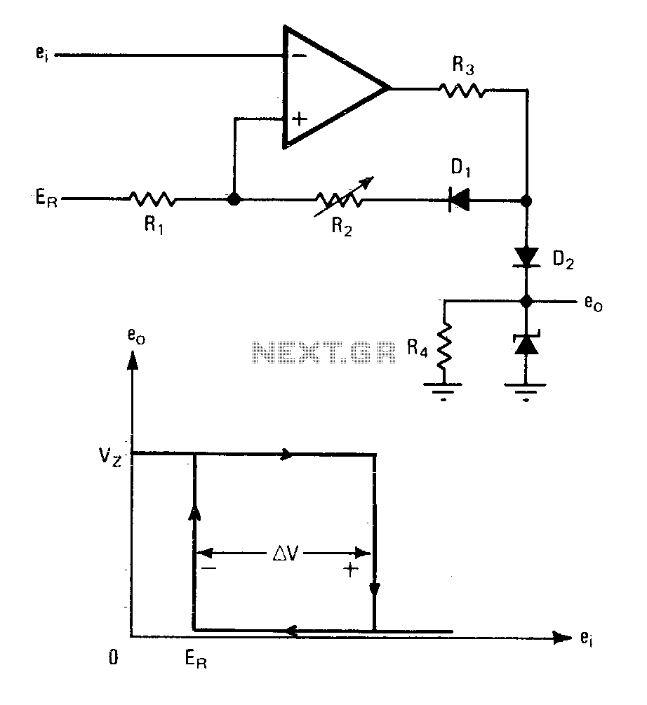
Comparator with variable hysteresis
An operational amplifier can be utilized as an effective device for analog comparator applications that necessitate two distinct trip points. The incorporation of a positive feedback network introduces a precise variable hysteresis into the conventional comparator switching action. This feedback...
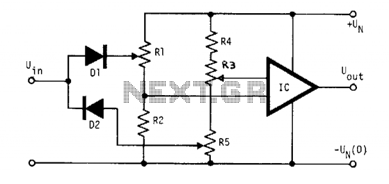
Hi-Low level comparator
The voltage to be compared is fed through diodes D1 and D2 to the voltage dividers R1 and R5, where the low and high limits are established. When the input signal voltage exceeds the high threshold limit set with potentiometer...
Frequency-detecting-comparator
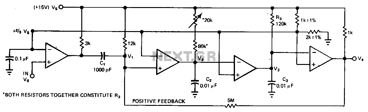
A quad comparator serves as the foundation for a frequency detector that is both faster and more cost-effective than more complex alternatives utilizing frequency-to-voltage converter chips. Positive feedback through a 5 MΩ resistor enables the circuit to detect changes as...

High input comparator
The circuit utilizes both halves of the CA3290 BiMOS dual voltage comparator. The LED will be activated whenever the input signal is above the lower limit (VL) but below the upper limit (Vy).
The circuit design employs the CA3290 BiMOS dual...
Power-supply-balance-indicator
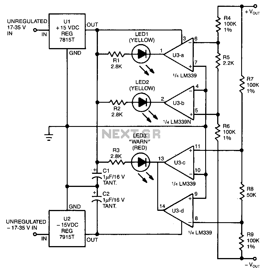
This circuit utilizes two pairs of comparators from an LM339N quad comparator. One pair controls the yellow positive (+) and negative (-) indicators, while the other pair drives the red warning LED3. The circuit is powered by the unregulated section...
IC Magnitude Comparators
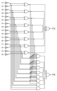
This Magnitude Comparator can be used to perform comparisons of two 8-bit binary or BCD words. The output provides both a P equals Q function and a P greater than Q function. A Magnitude Comparator is typically classified as standard...
Connection Tester
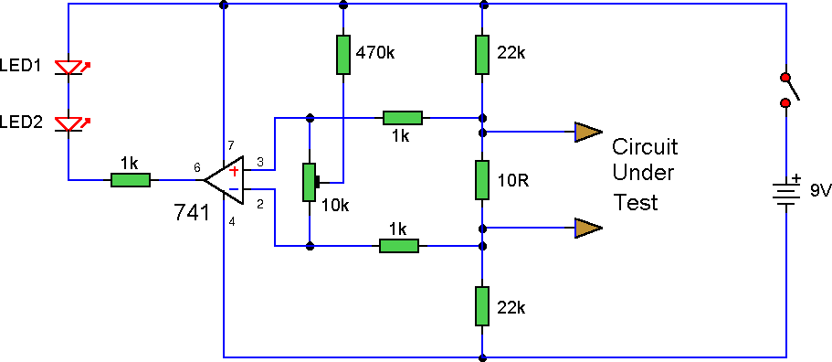
This circuit employs a 741 operational amplifier (op-amp) in differential mode to function as a continuity tester. The voltage difference between the non-inverting and inverting inputs is amplified by the op-amp's full open-loop gain. For the moment, the 470kΩ and...
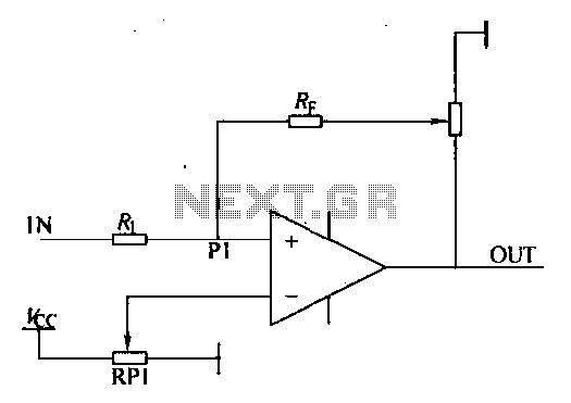
Loop comparator circuit
Environmental interference can affect the transfer switching, leading to the production of burrs in confidence disgrace. The switch position signal will control the computer system with the reliability of lanthanum burrs. The work has some impact. Glitches are typically addressed...