


Low battery indicator
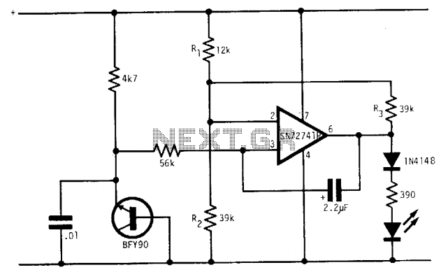
Description: Under optimal battery conditions, the LED remains off. As the battery voltage decreases, the LED starts to flash, and when the battery reaches a low voltage condition, the LED illuminates continuously. This circuit is designed for use with a 9-volt battery, and with the specified component values, the LED flashes when the voltage drops between 7.5 to 6.5 volts.
The circuit utilizes a BFY90 transistor, which acts as a switch to control the LED based on the battery voltage level. The transistor is configured in such a way that it remains off when the voltage is above 7.5 volts. When the voltage falls below this threshold, the transistor begins to conduct, causing the LED to flash intermittently. This flashing behavior serves as an early warning signal to indicate that the battery is nearing a low voltage condition.
As the voltage continues to drop to 6.5 volts or lower, the transistor remains fully on, allowing the LED to light continuously. This provides a clear indication that the battery is in a low voltage state and may require replacement or recharging. The integrated circuit used in this design is the SN72741P, which is responsible for monitoring the voltage levels and controlling the timing of the LED's flashing behavior.
The circuit can be further enhanced by incorporating additional components, such as resistors and capacitors, to fine-tune the flashing frequency and brightness of the LED. Proper selection of these components is crucial to ensure reliable operation across the specified voltage range. Additionally, the circuit layout should minimize parasitic capacitance and inductance to maintain performance, especially in portable applications where battery life is critical.Under good battery conditions the LED is off. As the battery voltage falls, the LED begins to flash until, in the low battery condition, the LED lights continuously. Designed for a 9-volt battery, with the values shown the LED flashes from 7.5 to 6.5 volts. The transistor is the BFY90 and the IC is the SN72741P.
The circuit utilizes a BFY90 transistor, which acts as a switch to control the LED based on the battery voltage level. The transistor is configured in such a way that it remains off when the voltage is above 7.5 volts. When the voltage falls below this threshold, the transistor begins to conduct, causing the LED to flash intermittently. This flashing behavior serves as an early warning signal to indicate that the battery is nearing a low voltage condition.
As the voltage continues to drop to 6.5 volts or lower, the transistor remains fully on, allowing the LED to light continuously. This provides a clear indication that the battery is in a low voltage state and may require replacement or recharging. The integrated circuit used in this design is the SN72741P, which is responsible for monitoring the voltage levels and controlling the timing of the LED's flashing behavior.
The circuit can be further enhanced by incorporating additional components, such as resistors and capacitors, to fine-tune the flashing frequency and brightness of the LED. Proper selection of these components is crucial to ensure reliable operation across the specified voltage range. Additionally, the circuit layout should minimize parasitic capacitance and inductance to maintain performance, especially in portable applications where battery life is critical.Under good battery conditions the LED is off. As the battery voltage falls, the LED begins to flash until, in the low battery condition, the LED lights continuously. Designed for a 9-volt battery, with the values shown the LED flashes from 7.5 to 6.5 volts. The transistor is the BFY90 and the IC is the SN72741P.
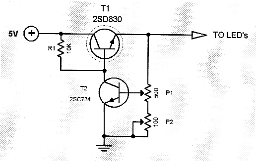
LED dimmer circuit
Typical segment display LEDs consume around 25 mA for each segment and should be limited to this current with resistors. For a six-digit display to be current limited, at least 42 series resistors are needed. The brightness of the LEDs...
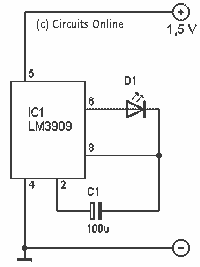
Easy 1.5 V LED flasher
This simple flash is very compact to build in such a brooch. I have the circuit extracted from a CD cover. The flash uses a 1.5 V supply, this is a penlight or a button cell to use. Capacitor C1...
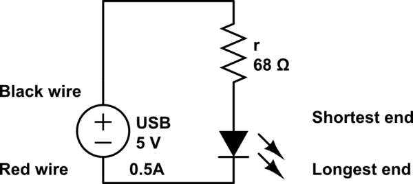
led How should I build this circuit
The LED operates at 3V, and based on information available online, a blue LED typically supports a maximum current of 0.03A. Given the available current from the USB source, the intention is to construct a parallel circuit. However, the last...
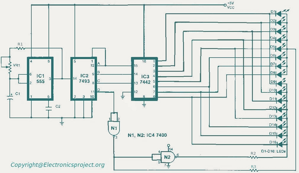
Led Running Lights
The circuit comprises three main components. The first component features an oscillator, while the second component includes a mod 16 counter (7493). The oscillator is configured in self-triggered mode, and a potentiometer (VR1) is utilized for speed control of the...
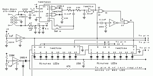
72 LED Clock
The circuit employs 60 individual LEDs to represent the minutes of a clock and 12 LEDs to indicate the hours. The power supply and time base circuitry are consistent with those described in the previous 28 LED clock circuit. The...
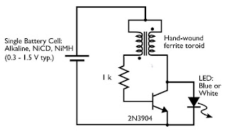
LED Flashlight Use Super capacitor Schematic Diagram
Tired of experimenting with capacitors? It's time to explore supercapacitors, which offer significant storage capabilities. This article provides instructions on building a small LED flashlight utilizing supercapacitors. A minimum voltage of 2 volts is necessary to illuminate the LED, as...
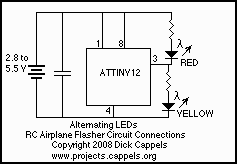
R/C Airplane LED Flasher
This was designed to flash a pair of LEDs to be mounted on the wing tips of a Parkzone Citabria R/C (remote control) airplane. The unmodified Parkzone Citabria only weighs 20 grams (about 0.7 oz), so weight, and therefore the...
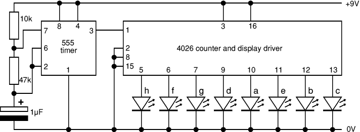
Random Flasher for 8 LEDs Project
This project flashes eight LEDs in a seemingly random manner. It utilizes a 4026 combined counter and display driver integrated circuit (IC) designed for driving 7-segment LED displays. The sequence is not entirely random, as seven of the LEDs represent...
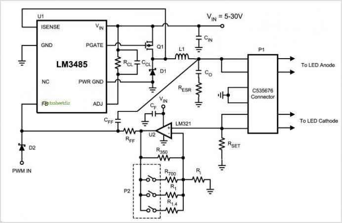
Lm3485 Led Demo Board
The LM4550 is an audio codec designed for PC systems, fully compliant with PC99 standards, and performs the analog-intensive functions of the AC97 Rev2.1 architecture. It utilizes 18-bit Sigma-Delta analog-to-digital (A/D) and digital-to-analog (D/A) converters, providing a dynamic range of...