


Make Lm324 Op Amp Swing Rail-To-Rail
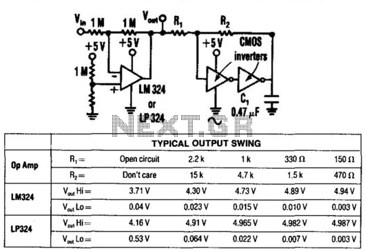
Description: By utilizing two CMOS inverters, the output voltage of an LM324 operational amplifier can be increased from 3.5 V peak-to-peak (Vpp) to 4.9 Vpp. This circuit is recommended solely for light loads (less than 30 mA) and for relatively slow operational amplifiers. Any CMOS inverter, such as the 74C00, 74C02, 74C14, CD4001, CD4011, etc., can be employed.
The circuit employs two CMOS inverters configured in series to amplify the output voltage from the LM324 op-amp. The LM324 is a versatile quad op-amp that typically outputs a maximum of 3.5 Vpp when powered by a standard dual supply. The use of CMOS inverters provides a means to boost this output to 4.9 Vpp, which can be beneficial in applications requiring higher voltage levels without significant power consumption.
The recommended load for this configuration is light, specifically under 30 mA, to prevent overloading the inverters, which could lead to distortion or failure. The choice of inverters is flexible, allowing for various models, including the 74C00, 74C02, 74C14, CD4001, and CD4011. These inverters are characterized by their high input impedance and low output impedance, making them suitable for this application.
In the schematic, the output of the LM324 is connected to the input of the first CMOS inverter. The output of this inverter is then fed into the input of the second inverter. The final output is taken from the output of the second inverter, which is now capable of delivering an increased voltage level. The power supply for the inverters should match their specifications, typically a dual supply of ±5V to ±15V, depending on the specific inverter model used.
It is crucial to ensure that the circuit is designed with appropriate bypass capacitors near the power supply pins of the inverters to maintain stability and reduce noise. Additionally, proper layout techniques should be employed to minimize parasitic capacitance and inductance, which can affect the performance of the circuit, especially at higher frequencies. By using two CMOS inverters, the output for an LM324 op amp can be increased from 3.5 Vpp to 4.9 Vpp. This circuit is only recommended for light loads (<30 mA) and for relatively slow op amps. Any CMOS inverter (74COO, 74C02, 74C14, CD4001, CD4011, etc.) can be used.
The circuit employs two CMOS inverters configured in series to amplify the output voltage from the LM324 op-amp. The LM324 is a versatile quad op-amp that typically outputs a maximum of 3.5 Vpp when powered by a standard dual supply. The use of CMOS inverters provides a means to boost this output to 4.9 Vpp, which can be beneficial in applications requiring higher voltage levels without significant power consumption.
The recommended load for this configuration is light, specifically under 30 mA, to prevent overloading the inverters, which could lead to distortion or failure. The choice of inverters is flexible, allowing for various models, including the 74C00, 74C02, 74C14, CD4001, and CD4011. These inverters are characterized by their high input impedance and low output impedance, making them suitable for this application.
In the schematic, the output of the LM324 is connected to the input of the first CMOS inverter. The output of this inverter is then fed into the input of the second inverter. The final output is taken from the output of the second inverter, which is now capable of delivering an increased voltage level. The power supply for the inverters should match their specifications, typically a dual supply of ±5V to ±15V, depending on the specific inverter model used.
It is crucial to ensure that the circuit is designed with appropriate bypass capacitors near the power supply pins of the inverters to maintain stability and reduce noise. Additionally, proper layout techniques should be employed to minimize parasitic capacitance and inductance, which can affect the performance of the circuit, especially at higher frequencies. By using two CMOS inverters, the output for an LM324 op amp can be increased from 3.5 Vpp to 4.9 Vpp. This circuit is only recommended for light loads (<30 mA) and for relatively slow op amps. Any CMOS inverter (74COO, 74C02, 74C14, CD4001, CD4011, etc.) can be used.
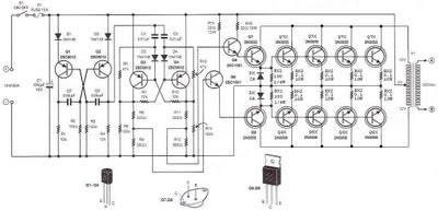
500 watt inverter 12vdc to 220vac
The step-up section of this inverter circuit utilizes a transformer with a 12V center-tapped (CT) secondary and a primary winding designed for 0 to 220V. The operating frequency is established by a flip-flop configured to 50 Hz.
The inverter circuit described...
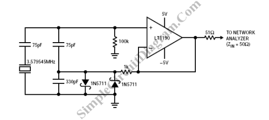
Op-Amp Colpitts Oscillator
A Colpitts oscillator can be implemented using an operational amplifier, provided that the op-amp has an appropriate bandwidth. An example of such a circuit can utilize the LT1190 or LT1191.
The Colpitts oscillator is a type of electronic oscillator that generates...
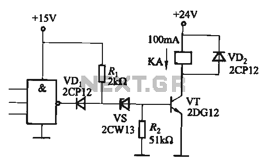
CMOS interface circuit and the switching amplifier
If the CMOS circuit load (actuator) is a relay device, the circuit must have a large load capacity. Non-gate drive switching amplifiers are connected to a separate element shown in the interface circuit.
In the context of a CMOS circuit where...
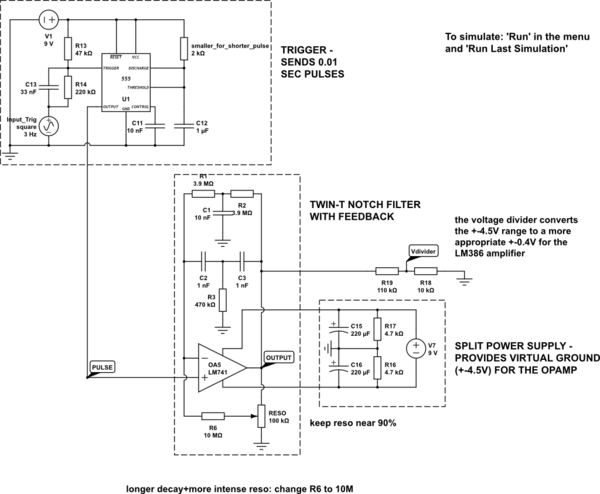
op amp Twin T circuit noisy
The circuit is constructed on a breadboard and produces the expected sound characteristics, specifically a damped sine wave reminiscent of large 808/909-style kicks. However, it exhibits a significant amount of noise. An attempt was made to mitigate this by adding...
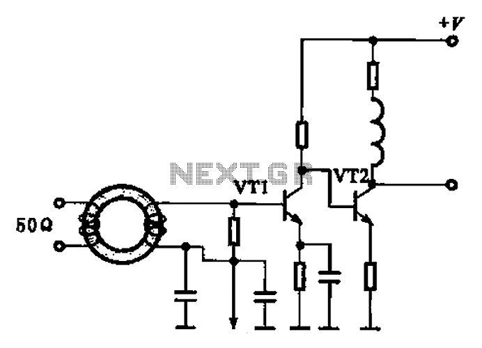
Broadband high frequency amplifying circuit
A broadband high-frequency amplifying circuit is primarily composed of a high-frequency matching transformer and an amplifying transistor. This circuit is designed to handle large high-frequency signals. The input of the amplifier circuit utilizes a matching transformer to ensure that the...
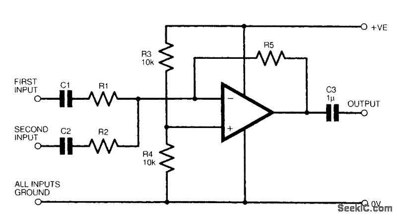
TWO CHANNEL AUDIO MIXER
The figure illustrates a fundamental two-channel operational amplifier (op-amp) mixer circuit. The gain for channel 1 is determined by the ratio of resistors R5 to R1, while for channel 2, it is determined by the ratio of R5 to R2....
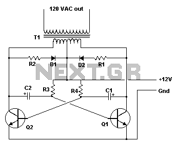
inverter circuit
This inverter is designed to operate appliances such as TVs and stereos while traveling or camping. It converts 12 VDC to 120 VAC, with the output wattage determined by the transistors used for Q1 and Q2, as well as the...
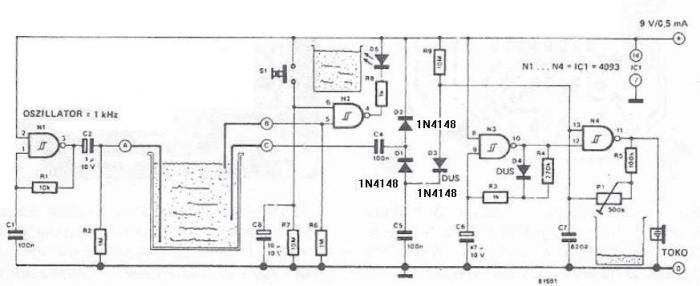
Hydro alarm circuit diagram using CMOS
The circuit diagram is straightforward and operates as follows: the N1 Schmitt trigger functions as an oscillator, producing a frequency of approximately 1 kHz. When there is sufficient water in the tank, alternating voltage flows from electrode A to electrode...
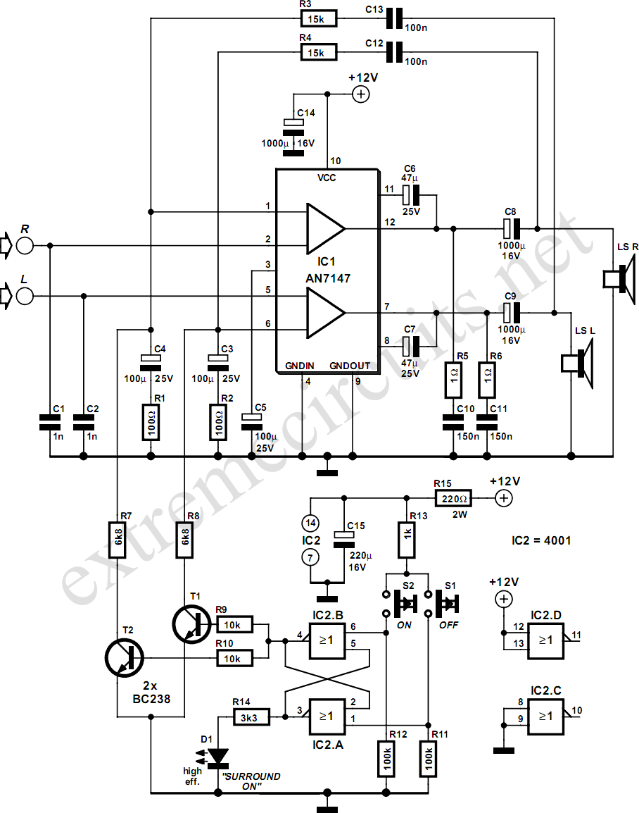
5.3W Amplifier With Surround System
The AN7147 Dual 5.3-watt Audio Power Amplifier from Panasonic is categorized as a replacement type, indicating its anticipated availability in the market for an extended period. When combined with additional components, it can be configured to create a simple surround-sound...